
C
Carolyn AndersonAug 1, 2025
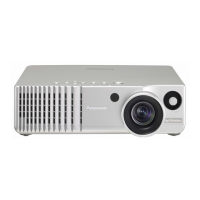
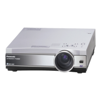
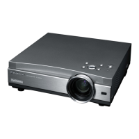
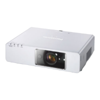
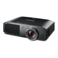
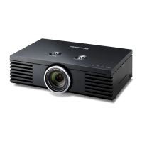
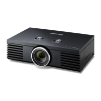
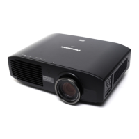
Why is the TEMP indicator flashing red on my Panasonic Projector?
- Llaurie87Aug 1, 2025
The TEMP indicator might flash red on your Panasonic Projector due to several reasons: * A connection problem or fault with the intake air temperature sensor (under -36 degrees C). * A connection problem or fault with the exhausting air temperature sensor (under -36 degrees C). * High environmental temperature or a closed intake air window (intake air temperature sensor: over 43 degrees C). * A closed ventilator or high altitude mode not being activated (exhaust air temperature sensor: over 79 degrees C). * Closed intake or high altitude mode not being activated (filter air temperature sensor: over threshold degrees C).