1 Safety Precautions 5
1.1. General Guidelines
5
1.2. Leakage Current Check
5
2 Specifications
6
3 Function for Safety
8
3.1. Temperature Detection inside the Lamp Unit
8
3.2. Interlock Switch
8
4 Serviceman Mode
9
4.1. Setting to Serviceman Mode
9
4.2. Resetting to User Mode
9
4.3. Functions in Serviceman Mode
10
5 Using the Serial Terminals
12
5.1. Examples of Connection
12
5.2. Pin Assignments and Signal Names
12
5.3. Communication Conditions (Factory Setting)
12
5.4. Basic Format
12
5.5. Procedure of Communication Condition Settings
13
5.6. Control commands
14
5.7. Cable specifications
17
5.8. Converting to RS-422 Control Functions
17
6 Using a Wired Remote Control
20
6.1. Connection Example
20
6.2. Setting the Projector ID Number for Remote Control
20
7 Support for Service
21
7.1. Supporting Methods
21
7.2. Note for Replacement of P.C.Boards
21
7.3. Service Kit (Extension Board) for X-P.C.Board
21
7.4. Replacement of the lithium battery on the R-P.C.Board
22
8 Cautions for Service
23
9 Parts Location
24
9.1. Electrical Parts Location
24
9.2. Electromechanical Parts Location
24
10 Replacement of Lamp Unit
25
10.1. Precautions on Lamp Unit Replacement
25
10.2. Timing of Lamp Unit Replacement
25
10.3. Lamp Monitor
26
10.4. Procedure of Lamp Unit Replacement
27
11 Disassembly Instructions
29
11.1. Flowchart for Disassembly
29
11.2. Air Filter Cleaning
30
11.3. Removal of Upper Cover
30
11.4. Removal of A-P.C.Board
31
11.5. Removal of S-P.C.Board
32
11.6. Removal of J-P.C.Board
33
11.7. Removal of G-P.C.Board
34
11.8. Removal of R-P.C.Board
35
11.9. Removal of X-P.C.Board
35
11.10. Removal of K-P.C.Boar d
35
11.11. Removal of Power Supply Block
36
11.12. Removal of PA-P.C.Bo ard
36
11.13. Removal of PC-P.C.Bo ard
37
11.14. Removal of PB-P.C.Bo ard
37
11.15. Removal of Ballast-1 Module
38
11.16. Removal of Ballast-2 Module
39
11.17. Removal of Analysis Block
40
11.18. Removal of DMD / Prism Block
42
12 Troubleshooting
44
12.1. Power Supply Checks
44
12.2. Signal Processing Circuit Checks
53
13 Interconnection Block Diagram
67
13.1. Interconnection Block Diagram (1 / 3)
67
13.2. Interconnection Block Diagram (2 / 3)
68
13.3. Interconnection Block Diagram (3 / 3)
69
14 Block Diagram
71
14.1. Power Supply
71
14.2. Signal Processing (1 / 2)
72
14.3. Signal Processing (2 / 2)
73
15 Schematic Diagram
75
15.1. A-P.C.Board (1 / 9)
76
15.2. A-P.C.Board (2 / 9)
77
15.3. A-P.C.Board (3 / 9)
78
15.4. A-P.C.Board (4 / 9)
79
15.5. A-P.C.Board (5 / 9)
80
15.6. A-P.C.Board (6 / 9)
81
15.7. A-P.C.Board (7 / 9)
82
15.8. A-P.C.Board (8 / 9)
83
15.9. A-P.C.Board (9 / 9)
84
15.10. G-P.C.Boa rd (1 / 2)
85
15.11. G-P.C.Boa rd (2 / 2)
86
15.12. J-P.C.Boar d (1 / 2)
87
15.13. J-P.C.Boar d (2 / 2)
88
15.14. K-P.C.Boar d
89
15.15. PA-P.C.Bo ard
90
15.16. PB-P.C.Bo ard
91
15.17. PC-P.C.Bo ard
92
15.18. R-P.C.Boa rd / S-P.C.Boar d
93
15.19. X-P.C.Boar d (1 / 3)
94
15.20. X-P.C.Boar d (2 / 3)
95
15.21. X-P.C.Boar d (3 / 3)
96
16 Circuit Boards
97
16.1. A-P.C.Board (Foil Side)
97
16.2. A-P.C.Board (Component Side)
98
16.3. X-P.C.Board,S-P.C.Board (Foil Side)
99
16.4. X-P.C.Board,S-P.C.Board (Component Side)
100
16.5. G-P.C.Board
101
16.6. PA-P.C.Board / R-P.C.Board (Foil Side)
102
16.7. PB-P.C.Board / R-P.C.Board (Component Side)
103
16.8. PC-P.C.Board
104
17 Terminal guide of ICs and transistors
105
18 Exploded Views
107
19 Replacement Parts List
111
CONTENTS
Page Page
3
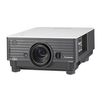
PT-D7700U / PT-D7700E
 Loading...