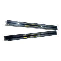
Before Using this Device
SF4C Safety light curtain
42
NOTE
The connectors can be distinguished by their color as follows:
• Connector for emitter: gray
• Connector for receiver: black
2.6.6 Basic Wiring
This is the general configuration using one set of an emitter and a receiver facing each other.
The control output (OSSD 1, OSSD 2) turns OFF if the light is blocked, while it automatically
turns ON if the light goes through.
The auxiliary output (Green/Black) has to be connected with the external device monitor
function (Green).
Feature Setting
Interlock function Inactive (Auto-reset)
External device monitor function Inactive
Auxiliary output Not available
Wiring for PNP output
K1
K2
+
%
-
+10
-15
24V
DC
(Brown) + V
(Pink) Test input / Reset input
(Pale purple) Interlock setting input
(Yellow) Override input
(Red) Muting lamp output
(Green / Black) Auxiliary output
(Gray) Safety input 1
(Gray / Black) Safety input 2
(Shield) Output polarity setting wire
(Blue) 0V
(Orange) Synchronization +
(Orange / Black) Synchronization -
(Orange / Black) Synchronization -
(Orange) Synchronization +
(Brown) + V
(Gray) Large multi-purpose indicator input 1
(Sky-blue / White) Muting input 1
(Green) External device monitor input
(Black) Control output 1 (OSSD 1)
(White) Control output 2 (OSSD 2)
(Shield) Output polarity setting wire
(Blue) 0V
(Gray / Black) Large multi-purpose indicator input 2
(Sky-blue / Black) Muting input 2
Gray cable
Gray cable
(with black line)
Emitter
Receiver
Rugghölzli 2
CH - 5453 Busslingen
Tel. +41 (0)56 222 38 18
Fax +41 (0)56 222 10 12
mailbox@sentronic.com
www.sentronic.com
Produkte, Support und Service
SEN
AG
 Loading...