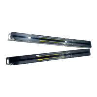
SF4C Safety light curtain
2.7 Wiring Examples
53
K1
K2
S1
S2
S2
S2
K1 K2
+
24V DC
%
-
+10
-15
(Brown) + V
(Pink) Test input / Reset input
(Yellow) Override input
(Red) Muting lamp output
(Green / Black) Auxiliary output
(Gray) Safety input 1
(Gray / Black) Safety input 2
(Shield) Output polarity setting wire
(Blue) 0V
(Orange) Synchronization +
(Orange / Black) Synchronization -
(Orange / Black) Synchronization -
(Orange) Synchronization +
(Brown) + V
(Gray) Large multi-purpose indicator input 1
(Sky-blue / White) Muting input 1
(Green) External device monitor input
(Black) Control output 1 (OSSD 1)
(White) Control output 2 (OSSD 2)
(Shield) Output polarity setting wire
(Blue) 0V
(Gray / Black) Large multi-purpose indicator input 2
(Sky-blue / Black) Muting input 2
Gray cable
EmitterReceiver
Gray cable
(with black line)
(Pale purple) Interlock setting input
Load
(Note)
Wiring for NPN output
Symbols in the wiring diagram
Switch S1
• Test input/Reset input • 0 - 2.5V (source current: 5mA or less): OFF
• Open: ON
Switch S2
• Muting input/Override
input
• 0 - 2.5V (source current: 5mA or less): OFF
• Open: ON
K1, K2 External device (forcibly guided relay or magnetic contactor)
Vs = Applied supply voltage
NOTE
• The OSSD output type (PNP or NPN) is determined by the connecting state of
the shield wire. Incorrect wiring may cause a lockout.
The following sections contain information about the proper adjustment and operation of the
safety light curtain.
You have to align the beam axis and test the light curtain in your application environment.
Rugghölzli 2
CH - 5453 Busslingen
Tel. +41 (0)56 222 38 18
Fax +41 (0)56 222 10 12
mailbox@sentronic.com
www.sentronic.com
Produkte, Support und Service
SEN
AG
 Loading...