6-2 Terminal Descriptions
512C Series Converter
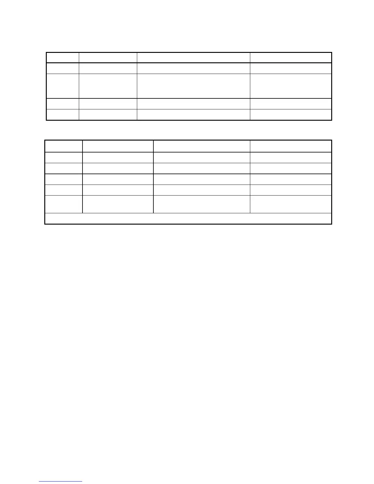
Power Terminals
Mains Supply Line2 Input or Neutral
Must also be used as Auxiliary
Supply Return when Auxiliary
Supply Input used.
Motor Armature Positive Output.
Motor Armature Negative Output.
Field Terminals (Auxiliary Supply)
Motor Field positive DC Output
Motor Field negative DC Output
Mains Supply Input Field Rectifier
Mains Supply Input Field Rectifier
Auxiliary Supply Input to Control
Transformer.
Auxiliary Supply Return via
L2/N
*
The signal applied to Aux L1 must be in phase with L1 in order to provide the correct coding for the controller.
This manual was downloaded on www.sdsdrives.com
+44 (0)117 938 1800 - info@sdsdrives.com