Fault Finding 7-1
512C Series Converter
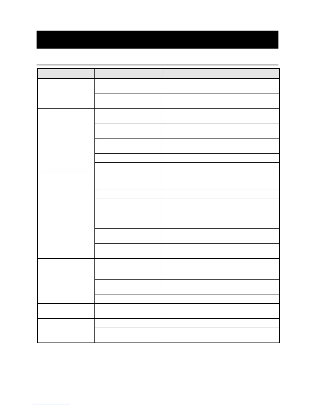
Chapter 7 FAULT FINDING
Troubleshooting
No "Power On" LED 2
Illuminated
Check Supply Availability and Supply Fuse fitted or
Circuit Breaker closed.
Incorrect Supply Voltage
Applied to Controller
Check Supply Voltage and Transformer Tapping
position are compatible.
Motor will not run at
Switch On
Start/Run Signal not present
Check Control Circuit Wiring
Check Total Setpoint terminal 12. Check Setpoint
Potentiometer & Wiring
Check P4 adjustment & External Current Limit
Potentiometer setting & wiring (if used)
Check Field AC Supply and Field connections
Motor Runs and Stops
after short period with
"Stall" LED1 Illuminated
Incorrect Current Limit Setting
Check P4 setting
Check external current limit setting
Incorrect Current Calibration
Check Programming Switches SW5,6,7
Incorrect Feedback Voltage
Calibration
Check Feedback Voltage Calibration Switches SW1/2.
Note These Switches must be set for both
Tachogenerator & Armature Voltage Feedback
Maximum Controller Output
Exceeded
Check compatibility of Motor Voltage to Controller
Output Voltage
Faulty Tachogenerator and/or
Coupling.
Check Tachogenerator (use Armature Voltage
Feedback Temporarily)
Motor runs at Full Speed
only
Incorrect Tachogenerator
Polarity or Open Circuit
Tachogenerator
Check Tachogenerator viability and connectivity
Open Circuit Speed Setpoint
Potentiometer
Check Terminal 13 or 10 as appropriate
Check Minimum Speed Potentiometer P6
Motor runs with Zero
Setpoint.
Zero Speed Offset Adjustment
Adjust P8 to give Zero Speed
No IR compensation for Tachogenerator Feedback.
Reduce P5 for Armature Voltage Feedback
This manual was downloaded on www.sdsdrives.com
+44 (0)117 938 1800 - info@sdsdrives.com