Pre-Installation Planning 2-1
514C Product Manual
Chapter 2 Pre-Installation Planning
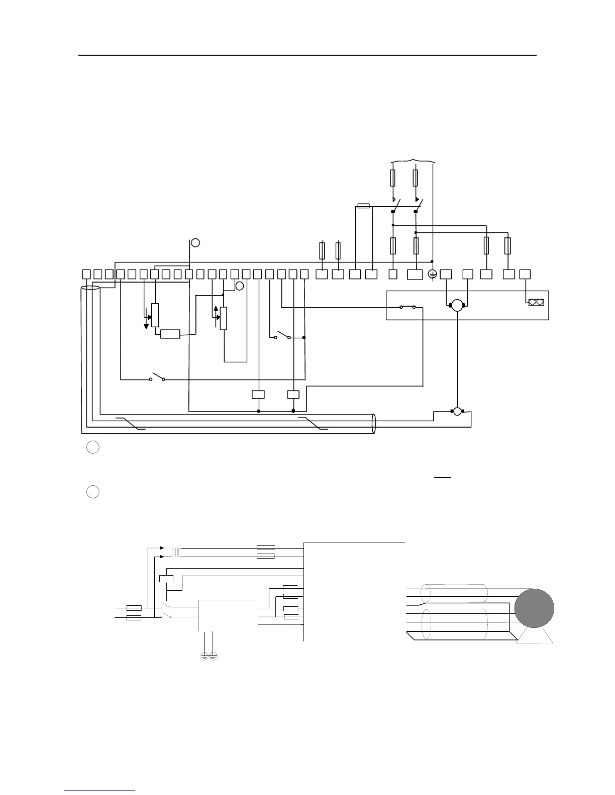
BASIC WIRING DIAGRAMS
Basic Connection
FS5 FS6
1 3 4 5 6 7 8 9 10 11 12 14 15 16 19 23 13
10K
SPEED
FS1
L1
L2/N
FS2
A4
RUN
TACHOGENERATOR
Branch Protection (Fuses or Circuit Breaker)
10K
10K
100%
CURRENT
LIMIT
EXTERNAL
(Optional)
SETPOINT
Speed Relay
Health Relay
PE
0 to
24
A3 A2 A1
AC Supply Contactor
22
Microtherm
A+ A-
F+ F- FL1 FL2
FS3 FS4
DC Motor
OPTIONAL
20
ENABLE
Auxillary AC Supply
Mains Supply
PE
GRD
Signal Ground
1
2
GND
It is recommended that the “0V/common” be connected to protective earth/ground for safety
reasons. In a system comprising of more than one controller, the 0V/common” signals
should be connected together and joined to protective earth/ground at one point only.
Stall override link between terminals 14 and 15 required when using controller in current
control.
EMC Connections With Filter
Product
L1
L2
PE
F+
F-
A+
A-
PE
PE
DC MotorScreened Cable
AC Supply
PE
FL1
FL2
Filter
Screened Cable
PE
A3
A4
A1
A2
This manual was downloaded on www.sdsdrives.com
+44 (0)117 938 1800 - info@sdsdrives.com

 Loading...