2-8 Pre-Installation Planning
514C Product Manual
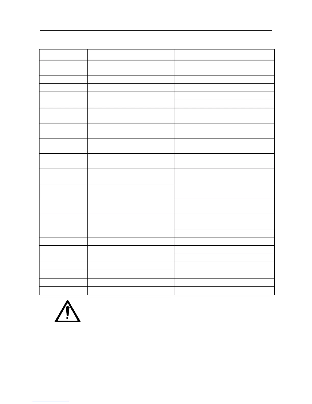
FUNCTIONAL DIFFERENCES 514C - 540
Inverse Time reduced Current
Limit.
Stall Detection & Timed Inhibit.
0.1 to 2 secs or 1 to 20 secs.
Ramp, Input No 1, Input No 2
and Inverted Input No 3.
Ramp, Positive Trim & Negative Trim
Input.
Auxiliary Current
Clamp Positive
Auxiliary Current Limit of Positive
Demand.
Auxiliary Current
Clamp Negative
Auxiliary Current Limit of
Negative Demand.
Speed Loop Current Demand
Output.
Current Demand O/P or Ext. Current
Demand I/P.
Isolates Speed Loop Current
Demand from Current Path.
External Current
Demand I/P
Additional Current Demand.
Current Demand O/P or Ext. Current
Demand I/P.
Enable Input of External Current
Demand.
External IR Compensation via
Armature Current Output.
Maintain for Momentary Start.
Output Source Short Circuit Protected.
Complies with EMC Directive.
Complies with Low Voltage Directive.
WARNING
THE 514C IS NOT A DIRECT REPLACEMENT FOR THE 540/1. IT IS
FUNCTIONALLY EQUIVALENT.
NOTE WHEN A 514C IS USED TO REPLACE A 540 WITH THE HEALTH AND/OR ZERO
SPEED RELAYS UTILISED, THE RELAYS MUST BE RECONNECTED BETWEEN
OUTPUT AND SIGNAL COMMON NOT +24V.
This manual was downloaded on www.sdsdrives.com
+44 (0)117 938 1800 - info@sdsdrives.com

 Loading...