Setting up & Commissioning 4-2
514C Product Manual
Current Calibration
Current Calibration is achieved using the BCD switches SW2, 3 and 4 where SW2 represents the
'Tens'; SW3 represents the 'Units' and SW4 represents the 'Tenths'. Thus a 16.5 amp calibration
is achieved by setting switch SW2 to 1, SW3 to 6, and SW4 to 5.
Please note that incorrect adjustment of these switches will cause excessive current to flow
which may cause damage to the motor and the controller. The absolute maximum setting
which can be set is 39.9 amps, this exceeds the Maximum Controller rating in all builds.
POTENTIOMETERS
Rotate Clockwise for Faster Acceleration to
Set Speed.
(Linear :- 1 to 40 seconds)
Rotate Clockwise for Faster Deceleration to
Set Speed.
(Linear :- 1 to 40 seconds)
Optimises Speed Loop Stability by
increasing gain.
Optimises Speed Loop Stability by
increasing integral time constant.
Rotate Clockwise to increase Maximum
Output Current.
With no additional connection to Torque /
Current Limit Terminal T7, the Upper Limit
is 110%. To achieve the 150% maximum
connect T7 to +7.5V.
Current Loop
Proportional
Optimises Current Loop Stability by
increasing gain.
Optimises Current Loop Stability by
increasing integral time constant.
Optimises speed regulation against load
change when using Armature Voltage
Feedback. Rotate Clockwise to increase
compensation and reduce regulation.
(Excessive adjustment may lead to
instability)
Controls Maximum Motor Speed. Rotate
clockwise to increase maximum speed.
Adjusts Zero for Zero Speed Setpoint.
Zero Speed
Sense
Threshold
Adjusts the Zero Speed sense Level for the
Zero Speed relay and Standstill Logic if
selected.
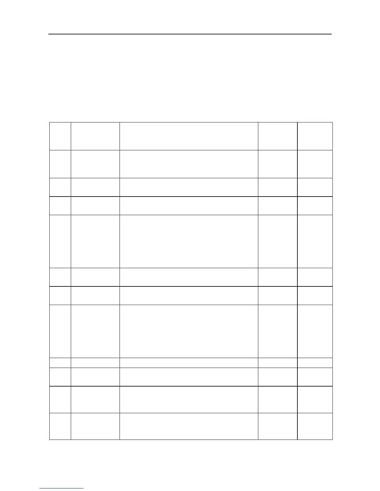
TABLE 4.3 Customer Adjustments.
This manual was downloaded on www.sdsdrives.com
+44 (0)117 938 1800 - info@sdsdrives.com

 Loading...