EasyManuals Logo

Parker 514C-04 User Manual

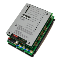
Parker 514C-04
43 pages
To Next Page IconTo Next Page
To Previous Page IconTo Previous Page
Page #8 background imageLoading...
Page #8 background image
1-2 Product Overview
514C Product Manual
PRODUCT IDENTIFICATION
FIELD TERMINALS
HEATSINK
LEGEND
PLATE
CONTROL
FIXING
POINTS
PCB
PROTECTIVE
GROUND
POWER
PCB
AUXILIARY
POWER
TERMINALS
SW2
SW3 SW4
1
ON
SW1
1 2 3 4 5 6 7 8 9 10
DIAGNOSTIC
SOCKET
Option Switches
Current Calibration
Switches
POTENTIOMETERS
DIAGNOSTIC LEDS
SUPPLY
AUXILIARY SUPPLY
SELECTOR SWITCH
24 23 22 21 20 19 18 17 16 15 14 13 12 11 10 9 8 7 6 5 4 3 2 1
L1 POWER ON
L2 STALL TRIP
L3 OVERCURRENT
L4 PLL LOCK
L5 CURRENT LIMIT
RAMP UP P1
RAMP DOWN P2
SPEED PROPORTIONAL P3
SPEED INTEGRAL P4
CURRENT LIMIT P5
CURRENT PROPORTIONAL P6
CURRENT INTEGRAL P7
IR COMPENSATION P8
P9
MAX SPEED CALIBRATION P10
ZERO SPEED ADJUST P11
ZERO SPEED THRESHOLD P12
A1 A2 A3 A4
CONTROL TERMINAL BLOCK
FL1 FL2 F- F+
L2/N L1 A+ A-
Tenths Unit Tens
This manual was downloaded on www.sdsdrives.com
+44 (0)117 938 1800 - info@sdsdrives.com

Questions and Answers:

Question and Answer IconNeed help?

Do you have a question about the Parker 514C-04 and is the answer not in the manual?

Parker 514C-04 Specifications

General IconGeneral
BrandParker
Model514C-04
CategoryController
LanguageEnglish

Related product manuals