Parker Hannifin Corporation
Chelsea Products Division
Olive Branch, MS 38654 USA
12
Bulletin HY25-1650-M1/US
Installation Sketch
NOTES:
1) Strip Wire Ends .25" Prior to Installing in Butt Connector (As Necessary)
2) Reference Kit 329076X
Electrical Ground
of Cab or Frame
Accepts .25" Screw
16 AWG Wire, Black
Connect To Ground
16 AWG Wire, Red
Connect to 12 VDC or
24 VDC, 5A Minimum
Ignition Circuit
2 Wire
Shielded
Cable
(1.0")
(1.8")
Electronic Overspeed
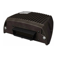
Controller - 329650X
(4.9")
Speed Sensor Extension Cable
328923-10X (10 Ft. Supplied w/E.O.C.)
328923-5X (5 Ft. Optional Cable)
Run Cable through
Grommet in Firewall
16 AWG Wire, Blue
with Butt Connector
16 AWG Wire, Green
with Butt Connector
Slice Grommet.
insert in Hole
in Firewall
379265
Grommet
Drill 1" Hole
in Firewall
“Blue” Wire
“Red” Wire
Saddle Splice Connector
Supplied by Installer
Wire “A” 16 AWG Wire
Supplied by Installer
379243
Speed Sensor
28-P-171
O-Ring
Rear Cover Shown in
“P” Option Position
Scale = 1:2
Hose per Chart
(Order Separately)
277/278/859
Series
Run Wires through
Grommet in Firewall
379504
Valve Connector
and Wire Assembly
“Black” Wire
Accepts #10 Screw
Electrical Ground
of Cab or Frame
379502
Pressure Switch
Rear Cover Shown in
Standard “P” Option Position
379486
90° Fitting Install in Transmission High Pressure Port
MD: Left or Right Side
HD: Left Side Only
Hose Per Chart
(Order Separately)
Electronic Over Speed Control (E.O.C.) Installation
Sketch for 277, 278 & 859 Series for Allison (SK-472)
Owner’s Manual
Electronic Overspeed Control
NOTE: Pre-2005 Connect to J1-6 (TCM) or Wire #106
2005 and Later - Connect 43 (TCM) or Wire #143

 Loading...


