English
6/20
ICEP080E-ICEP120E
4 Control
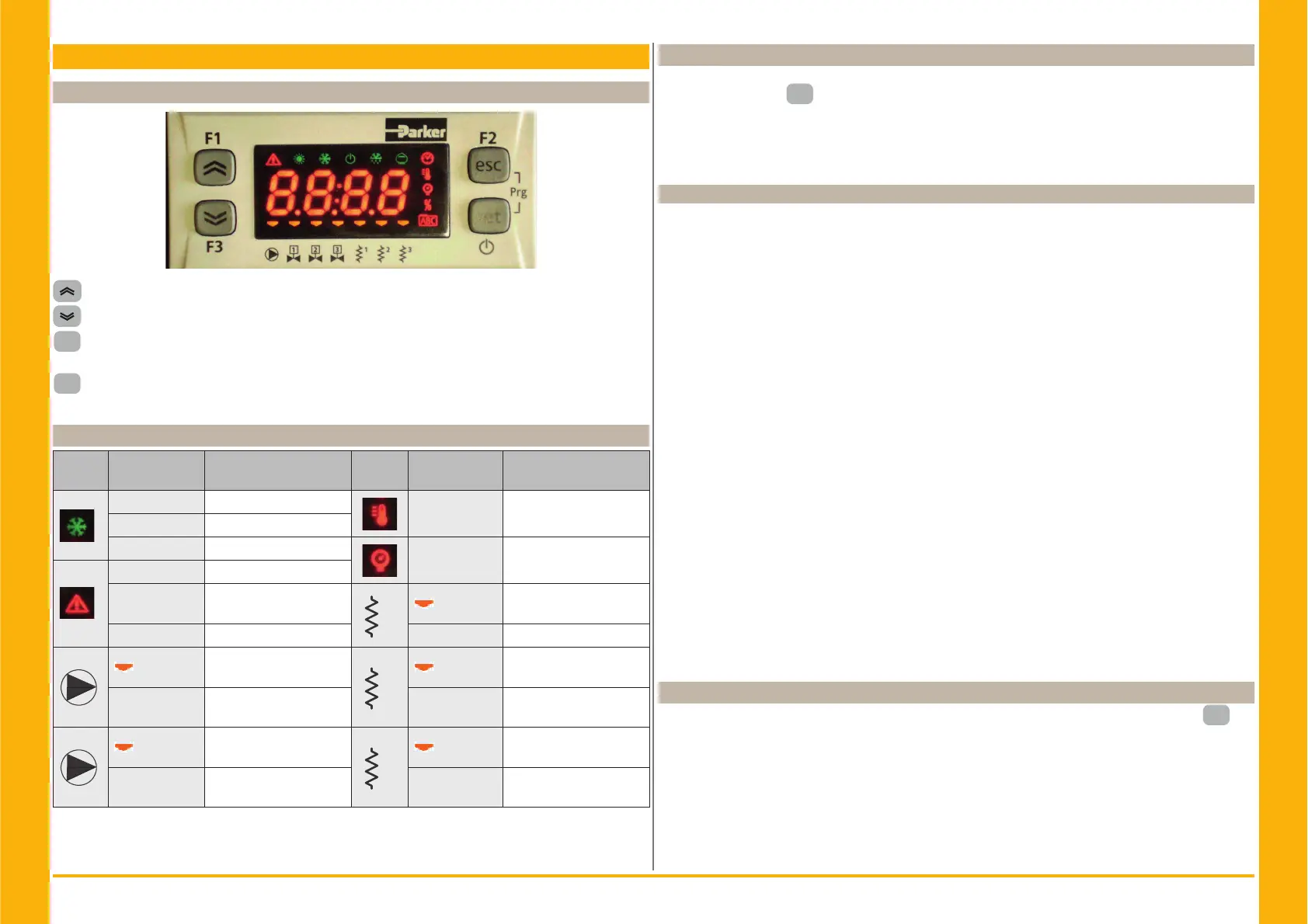
4.1 Control panel
UP button: press to increment the value of a selected, editable parameter.
DOWN button: press to decrement the value of a selected, editable parameter.
esc
ESC button : to exit without saving; returns to the previous level;
PRESSED FOR 5s. ALARM RESET.
set
SET button : to exit and saving/ confi rm the value; go to the next level; enter on Set Menu;
PRESSED FOR 5s. START CHILLER.
4.2 Meaning symbols
Symbol
Symbol
status
function Symbol
Symbol
status
function
Lit up Compressor ON
Lit up Temperature value
Flashing Compressor stand_by
Off Compressor Off
Lit up Pressure value
Lit up Allarm present
Flashing
Warning or
Alarm resetable
1
Lit up
Antefreeze heater ON
Off No alarm Off Antefreeze heater Off
1
Lit up
Pump 1 ON
2
Lit up
Crankcase heater ON
Compressor 1
Off Pump 1 Off Off
Crankcase heater Off
Compressor 1
2
Lit up
Pump 2 ON
(not present)
2
Lit up
Crankcase heater ON
Compressor 2
Off
Pump 2 Off
(not present)
Off
Crankcase heater Off
Compressor 2
4.3 Starting the chiller
1. Connect the power supply to the machine by turning the main isolator switch QS to ON.
2. Press the button “
set
” to start up.
3. Set the desired temperature on the controller. (par. 4.5.1)
Phases Monitor
If appears on display the alarm “
Er23“, during the start up, the user must verify the wiring of the
input terminals of the disconnecting switch.
4.3.1 Adjustments at commissioning
1. Water temperature setting, see heading 4.5.
2. Regolation of th pump
Verify correct operation of the pump, using the pressure gauge (read P1 and P0) and checking the
pressure limit values (Pmax and Pmin) indicated on the pump data plate.
P1 = pressure with pump ON
P0 = pressure with pump OFF
Pmin < (P1-P0) < Pmax
- Example n°1.
Conditions:
closed circuit, pressure P0 = 2 bar
pump data plate values: Pmin 1 bar/ Pmax 3 bar
adjust the valve outlet to give a pressure of 3 bar < P1< 5 bar
- Example n°2.
Conditions:
open circuit, pressure P0 = 0 bar
pump data plate values: Pmin 1 bar/ Pmax 3 bar
adjust the valve outlet to give a pressure of 1 bar < P1 < 3 bar
3. Verify correct operation of the pump similarly under normal running conditions.
Check also that the amperage of the pump is within the limits indicated on the data plate.
4. Switch off the chiller and proceed to top up the hydraulic circuit at the “SET” temperature.
5. Check that the temperature of the “treated” water does not fall below 5 °C and that the ambient
temperature in which the hydraulic circuit operates does not fall below 5 °C. If the temperature is
too low, add the appropriate quantity of glycol, as explained under heading 3.3.3.
Y ATTENTION !: before switching on the chiller pump, close the water outlet valve.
Always keep the possible inlet valve open, if present.
After switching on the pump, slowly open the chiller water outlet valve and adjust the fl ow rate as
described in point 4.3.1.
4.4 Stopping the chiller
When chiller operation is no longer required, turn the chiller off as follows: press the button “
set
”(5
Sec.) .
Do not turn off the main switch QS to ensure that any antifreeze protection devices will still receive
electrical power.