14
Voltage inputs
Instruction book, IQAN
Voltage inputs
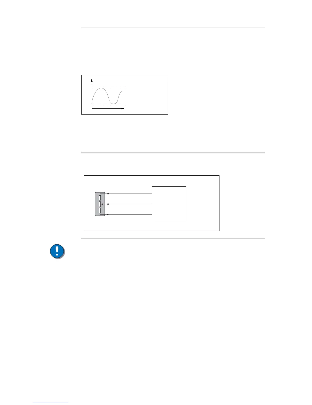
Connecting sensors to the voltage inputs
The sensor signal range must be 0-5 Vdc. To detect signal errors such as short circuits
or interruptions the active signal range be within 0.5-4.5 Vdc.
Active signal range.
The current consumption related to the voltage input is negligible.
The positive terminal of the sensor is connected to the +VREF position and the
corresponding negative terminal to the -VREF position. The sensor signal is connected
to appropriate VIN position.
NOTICE
The negative terminal of the sensor must not be connected to the chassis.
Maximum load for VREF position: see Appendix A.
Connecting other 3 wire sensors
The same type of connection shown for potentiometers is used for other 3 wire sensors
supplied with power from the regulated 5VDC supply, VREF. This includes active
temperature sensor IQAN-ST, pressure sensor IQAN-SP and Hall-effect levers IQAN-
LST or IQAN-LSL.
EXAMPLE
Connect the positive and negative terminals of the position sensor to +VREF,
and -VREF, respectively. Then connect the sensor signal to VIN-X.
Connecting VREF and sensor signal VIN-X.

 Loading...


