Parker Hannifin S.p.A. - Divisione S.B.C. LVD User’s Manual
8
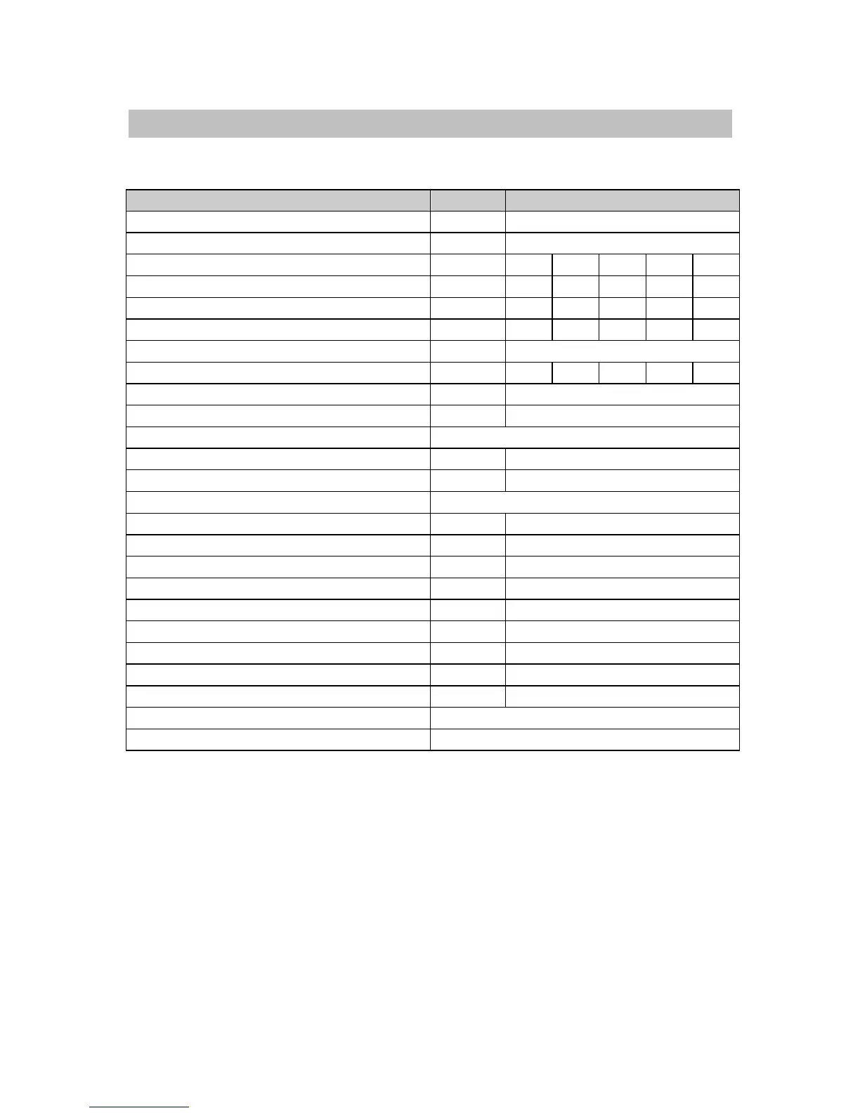
1.4 Main hardware specifications
Parameter U.M. Value
Power circuit power supply V~ 230 ± 10%
Control circuit power supply V= 24 ± 10% - 1.5A
Models
LVD1 LVD2 LVD5 LVD10 LVD15
Rated output current A 1.25
2.5 5 10 15
Peak output current (4 s) A 2.5 5 10 20 30
Output power at motor shaft kW .345
1.5 3 4.5
Dissipation from control electronics W 18
Dissipation from power stage W 18 28 45 87 120
Ambient temperature
o
C 45
Internal braking resistor dissipation W 120
Feedback resolver (speed 1)
Power stage switching frequency kHz 16
Maximum basic output frequency Hz 450
Protection category IP 20
24V digital inputs = N
o
8
24V digital outputs = / 100mA / PNP N
o
6
Voltage free contact digital outputs N
o
1
Encoder simulation RS-422
steps/rev
128..4096
Frequency / sign or encoder input kHz 800 / 200
Analog reference V ±10 diff 15 bit
Auxiliary analog input V ±10 diff 10 bit
Auxiliary analog output V ±10 - 8 bit
Tacho generator emulation output V ±10 V
Serial line RS-422 / RS-485
Field bus CanBus