Parker Hannin Corporation
Hydraulic Pump and Power Systems Division
Marysville, Ohio USA
Bulletin HY28-2708-02/SVC/EN | July 2019
Medium Pressure Axial Piston Pumps
P1/PD B-mod Service Information
40
11. Apply a light oil lm to the control piston (#15), and install it into the control
guide (#14) bore. Apply a light oil lm to the bias piston (#12). Install the bias
spring (#13) over the bias guide (#11) bore, and then slide the bias piston into
the bias guide bore.
12. For side ported non thru drive pumps, install the ripple chamber set screw
(#16) and plug (#19) and torque per the torque table values. For CW units, the
set screw is installed nearest to the locating pin. For CCW units, the set screw
is installed furthest from the locating pin. See Figure 6. Pumps that are end
ported or have a thru drive do not have a ripple chamber.
7. Apply a light oil lm into the piston bores of the barrel (#23). Lightly lubricate
the spherical surface of the spherical retaining plate washer (#25). Install the
nine pistons (#27) into the bores in the retaining plate (#26). Assemble the
spherical retaining plate washer into the retaining plate. While holding the
spherical washer against the retaining plate, slide the pistons into the barrel.
8. Install the two port block locating/dowel pins (#17) and the one port plate
locating pin (#7) into their respective locations on the port block (#3) face.
9. Install the port block control ow set screw (#6) in the proper location
depending on pump rotation. For proper location, see Figure 11 in the
rotation change section. The set screw should be installed in the passage
on the same side of the port block as the control piston.
10. For the 45cc pump, install unlubricated O-rings (#10) onto the control piston
guide (#14) and bias guide (#11). Next, apply Loctite Primer SF 194500 or
similar to the control piston guide and bias guide threads and allow it to
dry. The primer usually dries in about three minutes. Next, apply Loctite 263
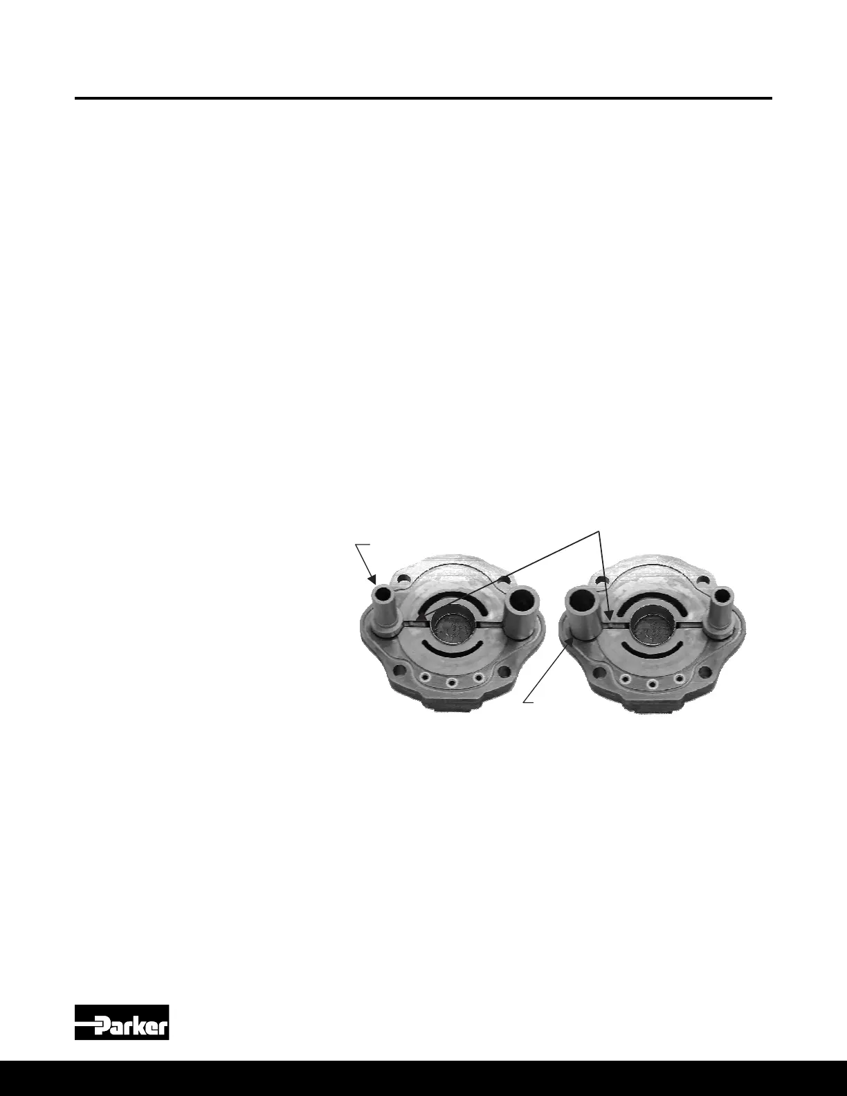
to the guide threads. For CCW rotation, install the bias guide (#11) nearest
to the locating pin (#17). See Figure 5A. For CW rotation, install the control
piston guide (#14) nearest to the locating pin (#17). See Figure 5B. Torque the
guides to 105 ft lbs. For the 18 and 28cc pumps, press the guides into the
port block.
NOTE: Torquing needs to be done in less than two minutes; otherwise, the
Loctite will set too soon and the guides will not be able to be fully torqued.
13. Apply a light film of oil into the piston bores. Lightly lubricate the spherical
surface of the guide ball. Install the nine pistons into the bores in the hold
down plate. Install the spherical guide ball into the hold down plate. While
holding the guide ball against the hold down plate, install the pistons into the
barrel.
14. Install the locating pin on the port block face.
15. Apply Loctite Primer Grade T to guide threads and allow to dry. Install
unlubricated o-rings on the control guide and bias guide. Apply Loctite 271to
guide threads. For left hand rotation the bias guide is installed nearest to the
dowel pin (figure 5A.) For right hand rotation the control guide is installed
nearest to the dowel pin (figure 5B.) Torque the control and bias guides as
16. Apply light oil film to control piston and install it in the control guide bore.
NOTE: The 140 had a lubrication hole in the piston. Confirm that the hole is
facing the port block. The control guide has nonsymmetrical lubrication
grooves. The end with the closest grooves must be installed towards the
port block.
17
. Apply light oil film to the bias piston. Install the bias spring and the bias
piston in the bias piston guide bore.
18. Apply a light layer of petroleum jelly to the back surface of the port plate.
Install the port plate on the port block, lining up the slot on the port plate with
the locating pin.
19. Install the large o-ring in the groove on the pump housing. Install the three
Teflon o-rings in the pressure communication ports on the pump housing.
20. Install the cam bearings in the cradle area of the housing. The chamfer on
the back of the bearing must face the outer wall of the housing. Use Loctite
Primer Grade “T” or other suitable primer on screws and mating threads in
housing. Apply Loctite #242 (use sparingly) to screw threads and install
orifice screws to hold bearings in place. Torque screws to 3.4 0.25 Nm (33
3 in-lb).
21. Place thin film of clean oil on cam bearing surfaces. Install cam in housing.
The cam must be tilted to permit entry into the housing. (Figure 2) NOTE:
The large pocket on the bottom surface of the cam must be on the same
side as the three pressure communication holes on the main housing. Pump
rotation does not affect the assembly of the cam.
22. Install the drive shaft into the pump housing. Position pump horizontally.
Install the rotating group over the pump shaft. Rotate the barrel to insure that
it is seated against the cam. Insure that the pump shaft is seated properly in
the front bearing.
Figure 5A
Port Block with Left
Hand Configuration
Figure 5B
Port Block with Right
Hand Configuration
specified in Chart 3.
Locating Pin
Bias Piston
Guide
Control Piston
Guide
Chart 3
Pump Control and bias
guide torque
045
045 Picture
Figure 5A
Port Block with Left
Hand Conguration
Figure 5B
Port Block with Right
Hand Conguration
Pump Assembly Procedures
(Continued)
018, 028, 045 Assembly Procedures

 Loading...


