Parker Hannin Corporation
Hydraulic Pump and Power Systems Division
Marysville, Ohio USA
Bulletin HY28-2708-02/SVC/EN | July 2019
Medium Pressure Axial Piston Pumps
P1/PD B-mod Service Information
42
NOTE: Make sure the Loctite does not get in the orice hole in the cam
bearing screws.
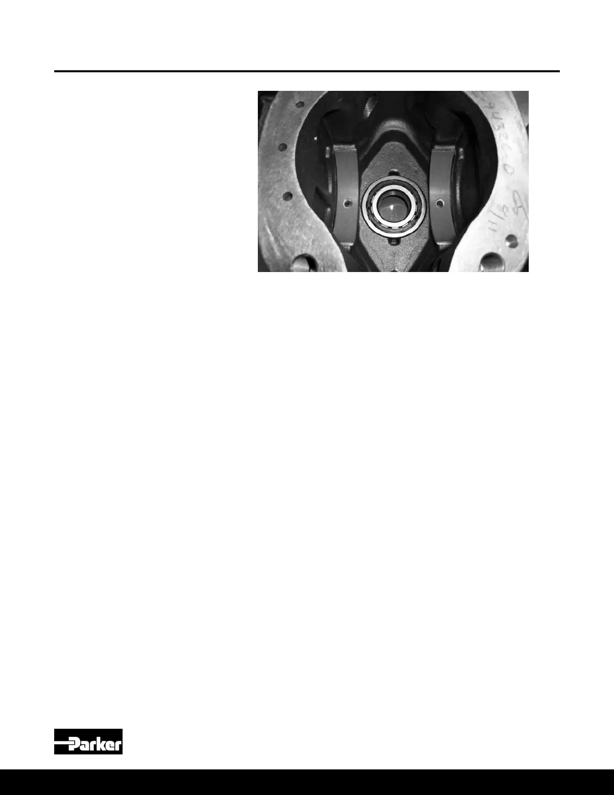
18. Place thin lm of clean oil on the cam bearing (#31) surfaces. Install the cam
(#29) in the housing. For the 45cc pump, the cam must be tilted to permit
entry into the housing. See Figure 2.
NOTE: The large pocket on the bottom surface of the cam must be on the
same side as the three pressure communication holes on the main housing.
Cam assembly is not affected by pump rotation direction.
19. Position the pump horizontally and install the rotating group into the pump
housing over the pump shaft (#28) and against the cam (#29) with tool T6 in
place in the center of the barrel (#23). Remove tool T6 as the barrel is slid
onto the shaft. This ensures all three barrel pins (#24) are held in place as the
rotating group is installed on the shaft.
20. Carefully install the assembled port block (#3) on the pump housing. Press the
port block to compress the bias spring (#13) and install the four housing bolts
(#1). Tighten the bolts in a cross pattern to ensure that the port block does
not get cocked on the housing. When the port block is seated on the housing,
torque the bolts in a cross pattern per the values in the Table 3.
21. On the 18 & 28cc units, install the M6x6 set screw with orice (#38) into the
BG port in the housing (#35) if it was removed during disassembly.
22. Install any boss plugs (#2, 5, 36 & 37) that were removed during disassembly.
23. Install ve O-ring seals and assembled compensator (#41) on the side of the
pump housing. Tighten the compensator bolts hand tight, and then torque the
bolts per the values in the torque table on page 13.
Figure 8 - Cam Bearings
Pump Assembly Procedures
(Continued)
018, 028, 045 Assembly Procedures

 Loading...


