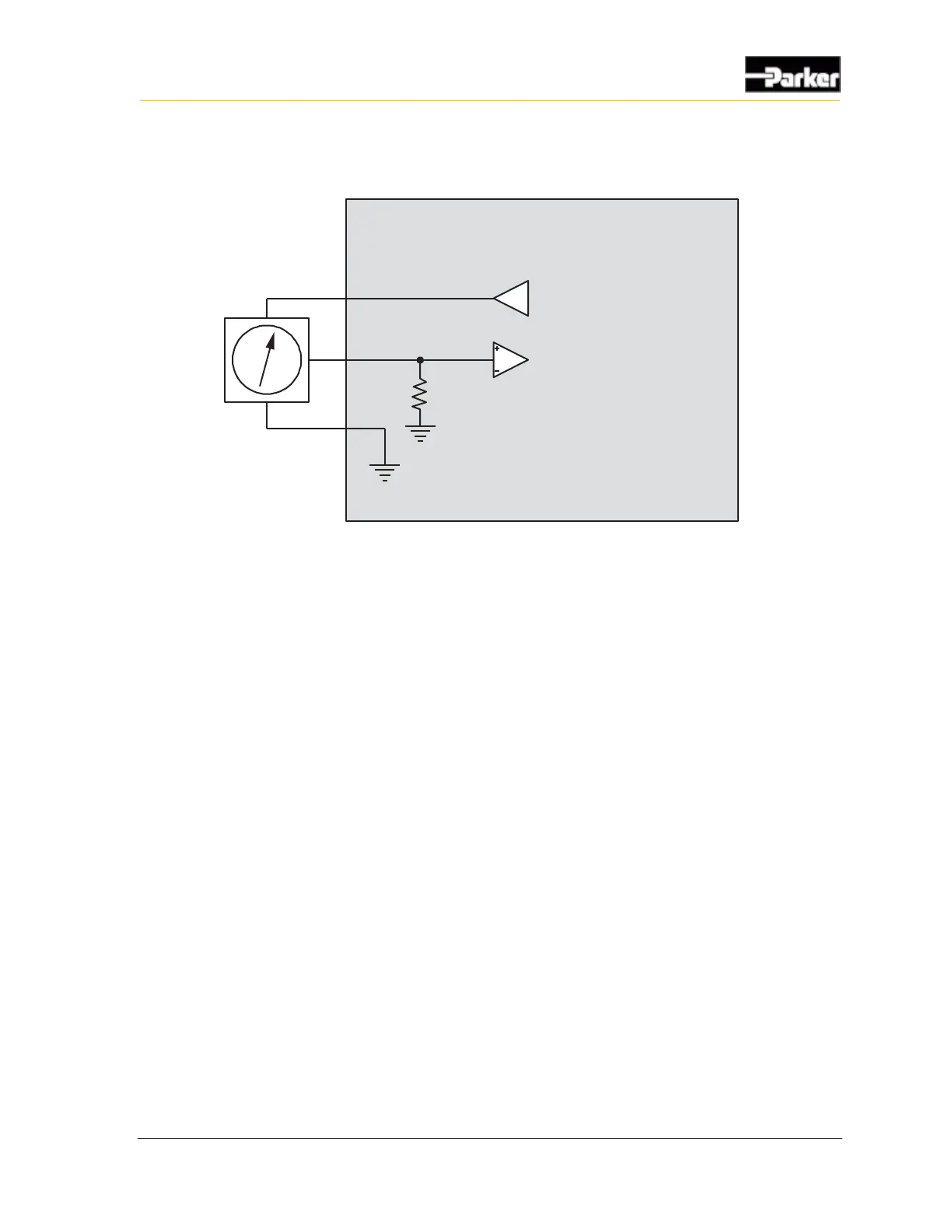
Figure 6: Analog input system noise reduction
Ground level shift
To reduce ground level shift:
1. Dedicate one of the <Number GND> system ground inputs (GND) to sensors
that have dedicated ground wires, and connect all sensor grounds to this
system ground input.
2. Splice the other system ground inputs together in the vehicle harness (close to
the connector) to provide a better ground for the noisier low-side outputs and
digital circuits.
3. Position the sensor’s ground connection near the system ground connections
to ensure that the signal remains within the digital activation range of the
input.
Note 1: The system ground inputs are rated for low-current signals, which
ensures the sensor's ground is very close in voltage potential to the system
ground.

 Loading...


