Serial Ethernet Recovery Flexcan (SERF) Development Board
Connector for Ethernet to the
PHD.
Not enabled on the Standard products, intended for
future use.
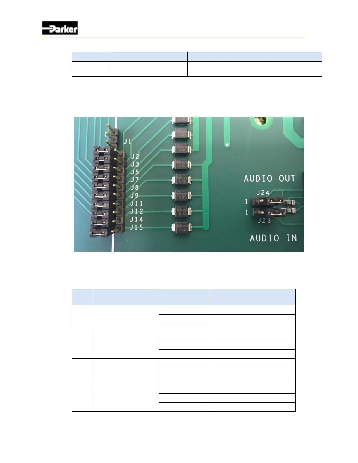
8.2.2. Jumpers
Figure 16: GPIO and audio jumpers
The following table describes the corresponding jumpers associated with each
I/O.
Enable GPIO switch input.
Intended for factory use.
Enable daughter board input.
Enable GPIO switch input.
Intended for factory use.
Enable daughter board input.
Enable GPIO switch input.
Intended for factory use.
Enable daughter board input.

 Loading...


