Serial Ethernet Recovery Flexcan (SERF) Development Board
8.2.1. Switches and Connectors
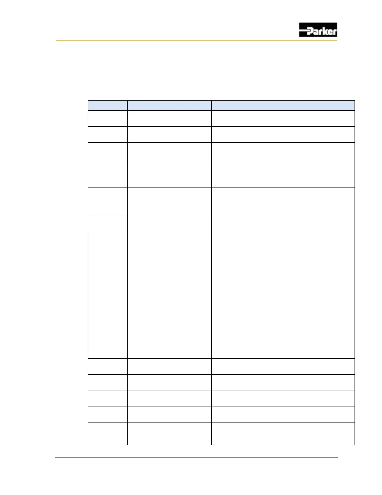
The following table describes the corresponding ports and switches associated
with each I/O.
Turns on and off power to the
PHD, 9-32VDC
Power is supplied through JP1 connector. Turns on
Power, but cannot be used as a wake signal.
Connector is reserved for factory use
Connector for RS232
communication to PC. Note: an
adapter may be required.
Intended for output strings from Lua scripts. For
debugging during development.
Connector for CAN
Communication to PC. Note: an
adapter may be required.
Intended for tracing CAN messages or inserting CAN
messages to the PHD for development.
General Purpose I/O inputs.
Used to switch the GPIO to VBATT (high), GND (low) or
floating state during development.
Note: the corresponding jumpers must be positioned as
shown in Jumper section.
Multi pin connector to the PHD.
Main connector to the PHD connector(s).
Connects USB_VBUS for
Recovery, Programming, or
Normal modes.
Switch to V_RCV for recovery mode (>+6Vdc).
Switch to V_USB (+5Vdc) to program PHD28 and
PHD70.
Leave in Neutral to program PHD50 and for normal
operation.
Recovery Switch Operation:
1. With the Power Switch OFF, Place Recovery
Switch in neutral position.
2. Power up the PHD.
3. Place the recovery switch in V_USB position.
4. Send the application file.
5. PHD should reboot in about 20-30 seconds after
the file is sent.
Keep the Recovery Switch in neutral position for normal
boot mode. The V_RCV position is for factory use only.
Connector for analog cameras.
Used to provide video input from the analog camera to
the PHD.
Connector for audio input and
output for the audio.
Not enabled on the Standard products, intended for
future use.
Connector for USB to PC or
memory stick.
Intended for application downloads from a PC or USB
memory stick in development.
Connector for USB to the PHD.
Intended for application downloads from a PC or USB
memory stick in development.
Connector for Ethernet
connection to PC, gateway or
bridge.
Not enabled on the Standard products, intended for
future use.

 Loading...


