EasyManuals Logo

Parker PHD Series User Manual

Parker PHD Series
58 pages
To Next Page IconTo Next Page
To Previous Page IconTo Previous Page
Page #26 background imageLoading...
Page #26 background image
18 PHD
Inputs
Note 2: Sensors that don’t have a dedicated ground wire are typically
grounded to the vehicle chassis through the sensor’s body.
Internal to product
Sensor Power
Resistive Sensor
Pull-up
Resistor
Active Sensor
Analog Input
Analog Input
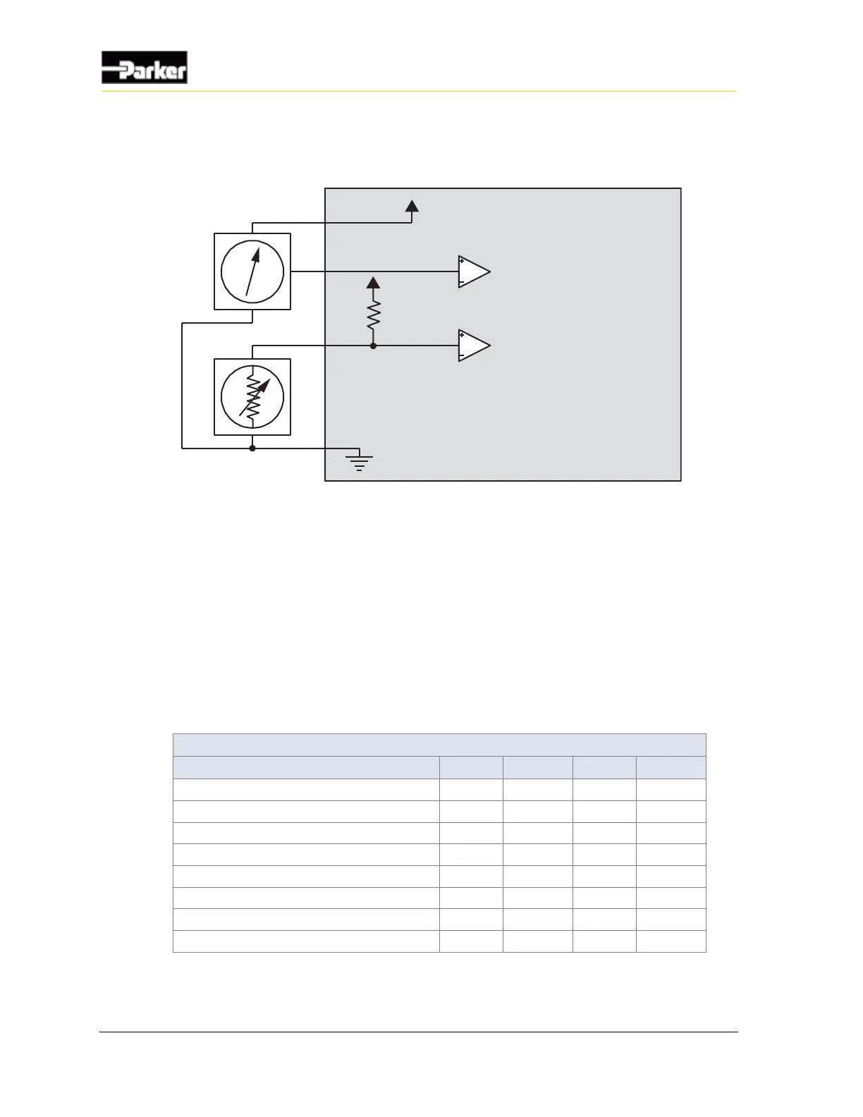
Figure 7: Analog input ground shift connection for sensors that have dedicated ground wires
3.3.2. PHD28/PHD50/PHD70 digital input capabilities
All of the PHD family of displays have digital inputs that can be configured as
active high or active low. The digital inputs can also be configured as other types
of inputs.
The number of digital inputs depends on PHD model and configuration using the
software tool.
The following table provides specifications for the PHD's digital inputs:
Digital Input Specifications
Item
MIN
NOM
MAX
UNIT
Input voltage range
0
32
V
Pull-down resistance
26.2
Pull-up resistance (to 4.3V min / 5V max)
1.2
Negative threshold
1.545
V
Positive threshold
4.008
V
Cutoff frequency (hardware)
1590
Hz
Over-voltage
36
V
Wetting current (through pull-up)
4.3
mA

Questions and Answers:

Question and Answer IconNeed help?

Do you have a question about the Parker PHD Series and is the answer not in the manual?

Parker PHD Series Specifications

General IconGeneral
BrandParker
ModelPHD Series
CategoryControl Unit
LanguageEnglish

Related product manuals