6.1.2. PHD CAN installation connections
The CAN connection for the PHD should conform to the J1939 standard. The
J1939 standard is a robust automotive specification that is a good CAN
installation guideline even when the J1939 CAN protocol is not being used.
For a list of J1939 connection considerations, refer to the SAE J1939
specifications available through the Society for Automotive Engineers. SAE
J1939-11 covers the physical aspects of the CAN bus including cable type,
connector type, and cable lengths.
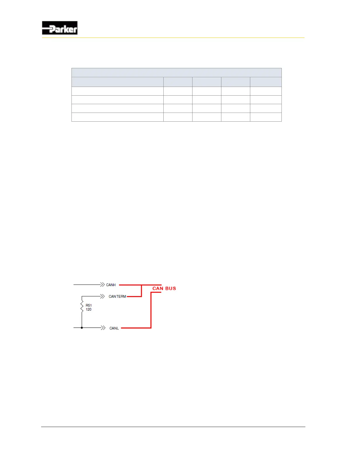
Note: The standard variant of the PHD does not have a CAN termination
resistor, which is based on the assumption that the CAN bus is terminated in
the harness. The PHD displays have a CAN termination pin that allows the
internal termination resistor to be applied. To implement the internal CAN
termination resistor, The CAN_TERM pin should be wired as shown.
Figure 12: PHD CAN_TERM wiring

 Loading...


