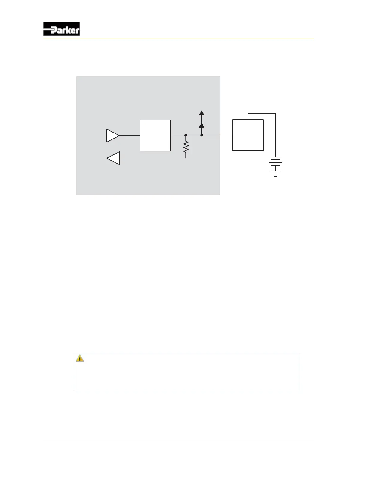
Figure 11: Low-side outputs with current sense installation connections
4.2. Sensor and regulated supply outputs
The PHD has 2 types of sensor supply pins, labeled USB_VBUS, P5V0 and P12V0
dedicated to providing power to external sensors and devices.
▪ 5V USB or sensor supply
▪ 12V regulated supply
The PHD28 has 1 of each type of supply:
▪ USB_VBUS / P5V0 is a 5V supply
▪ P12V0 is a 12V regulated supply
The PHD50 and PHD70 have 2 x 5V and 1 x 12V supplies:
▪ USB_VBUS and P5V0 are 5V supplies
▪ P12V0 are 2 pins assigned to the 12V regulated supply
Warning! Do not drive more than 500 mA of current through the
combined pins. Doing so will cause the pins to protect themselves by
dropping the voltage, which will result in a lack of power to the sensors
and other devices, causing unknown vehicle responses.

 Loading...


