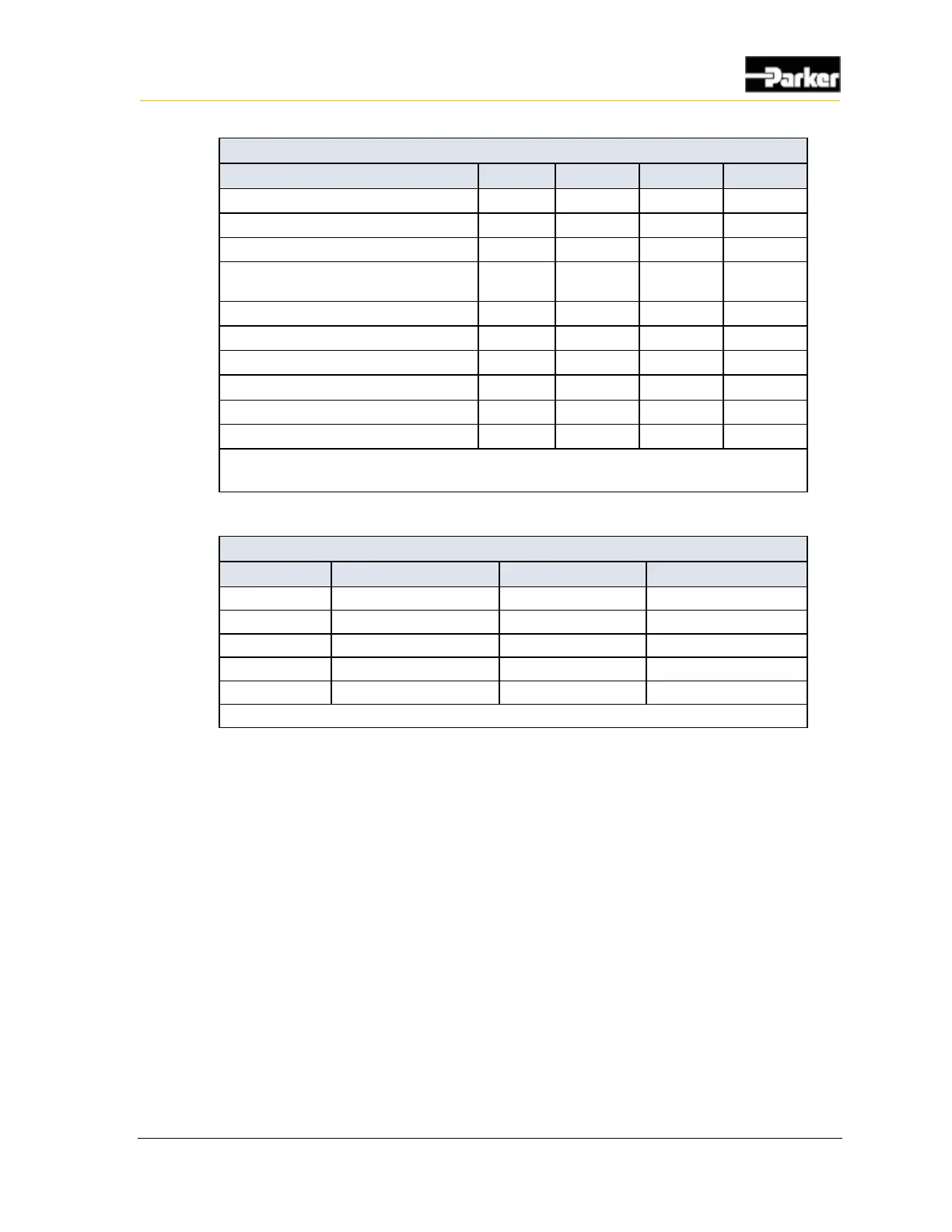
Low-Side Output Parameters
Max. voltage applied to pin
Current limit in short-to-ground
condition
Pull-down resistance (PHD28/50)
Pull-down resistance (PHD70)
Feedback gain (V
micro
/V
pin
) (see note)
Feedback max readable voltage
Feedback cut-off (3dB) frequency
Note: V
micro
is the voltage at the micro A/D pin, and V
pin
is at the external connector pin. The
tolerance of the V
pin
measurement using nominal gain is ±0.5 V.
Low-Side Output Error Detection
Note: An over-temperature fault results in driver output cycling.
4.1.1.1. Low-side output connections
When connecting low-side outputs, note that
▪ low-side outputs are connected to a common internal ground point that is
connected to the battery ground (GND).
▪ low-side outputs provide switched ground to any load type in a vehicle.
▪ low-side outputs can sink up to 0.5 A.
When connecting a load to a low-side output, ensure that the load will not drive
currents greater than the maximum specified peak current or the maximum
specified continuous current.

 Loading...


