To reduce ground level shift:
▪ If there are more than 1 GND pins in the system, dedicate one of them to
sensors that have ground wires, and connect all sensor grounds to that system
ground pin.
▪ Splice the other system ground inputs together in the vehicle harness (close to
the connector), to provide a better ground for the noisier low-side outputs and
digital circuits.
▪ Ensure the sensor’s ground connection is close to the system ground
connections. This will help ensure the signal remains within the digital
activation range of the input.
Note 1: The PHD system ground inputs are rated for low-current signals,
which ensures the sensor’s ground is very close in voltage potential to the
system ground.
Note 2: Sensors that don’t have a dedicated ground wire are typically
grounded to the vehicle chassis through the sensor’s body.
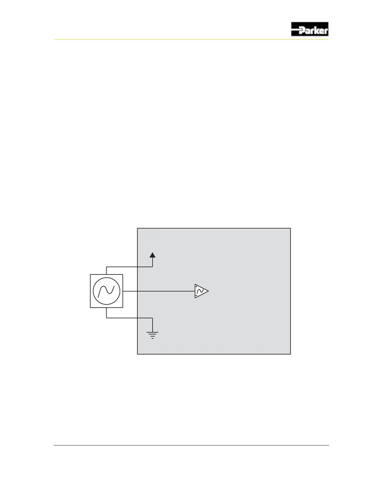
The following shows a typical DC-coupled frequency input connection:

 Loading...


