19
External I/O Connector: DB37 connector used to interface with various devices, allowing
up to three 4-20 ma Analog inputs (A1, A2 & A3) for recording data or alarming based upon
that data. It also allows an interface with Parker foot switch (P/N: 080-059) and allows
remote Start / Stop control of the FilterTec Plus.
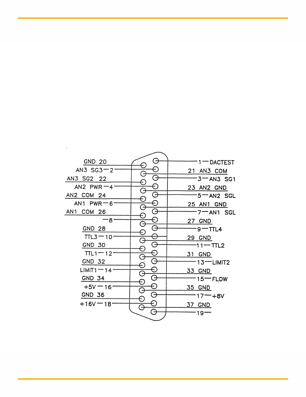
For pin configuration, consult the drawing on this page. The DB37 port at the back panel
provides three analog input channels for devices providing loop power:
Analog channel 1 (pin 7 signal, pin 25 ground)
Analog channel 2 (pin 5 signal, pin 23 ground)
Analog channel 3 (pin 2 signal SG3, pin 21 common)
When a Footswitch or External Run / Stop Cable is desired, Pins 19 and 37 are used.
Pin out of DB37 External I/O Connector on Rear Panel: