50 CHAPTER 4 LOCATING THE PROBLEM
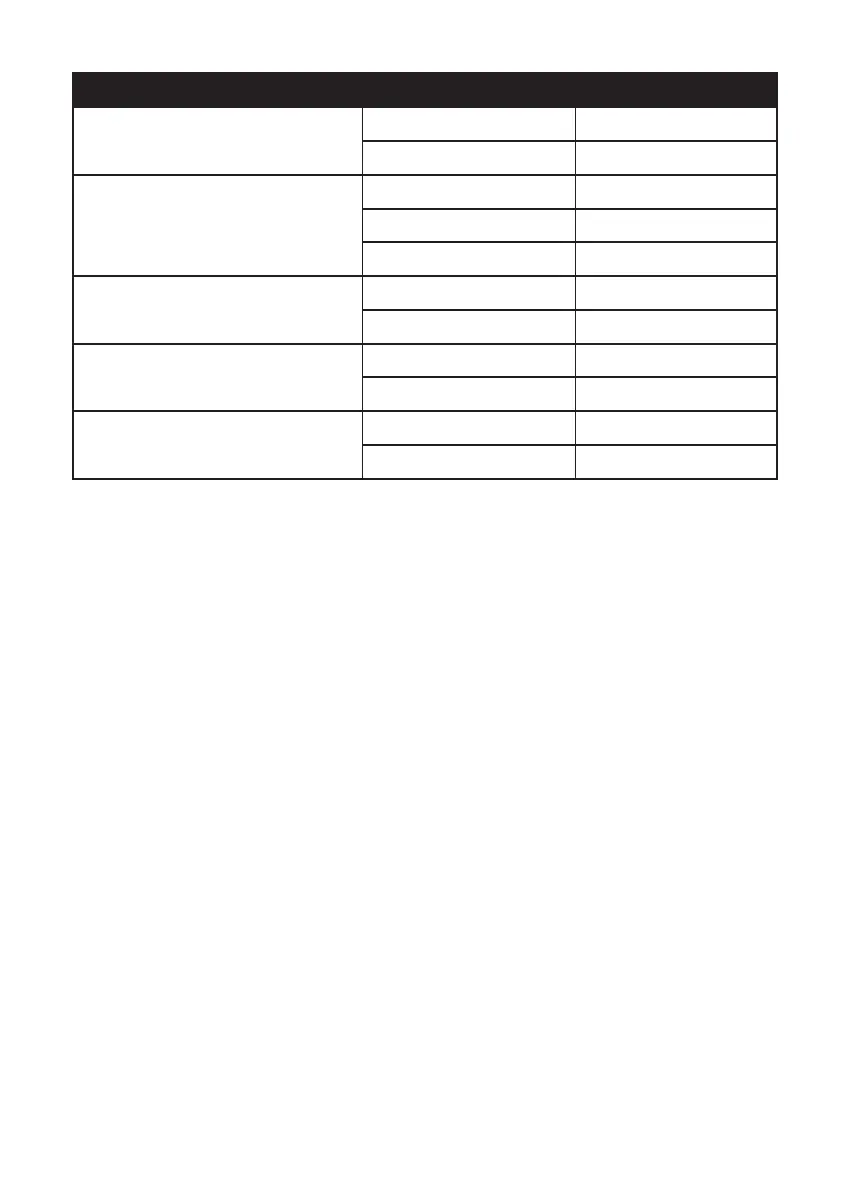
Jumper Setting Description
J1
CN17 USB Power selection
1-2 (default) 5V
2-3 3.3V
JP2/JP3
Switch headers for COM3/COM4 pin9
1-2 5V
3-4 (default) RING
5-6 12V
JLV1
LCD backlight inverter power selection
1-2 5V
2-3 (default) 12V
JLV2
LCD panel power selection
1-2 (default) 3.3V
2-3 5V
JLV3
Backlight control mode selection
1-2 (default) Voltage level mode
2-3 PWM mode