www.parweld.com
17
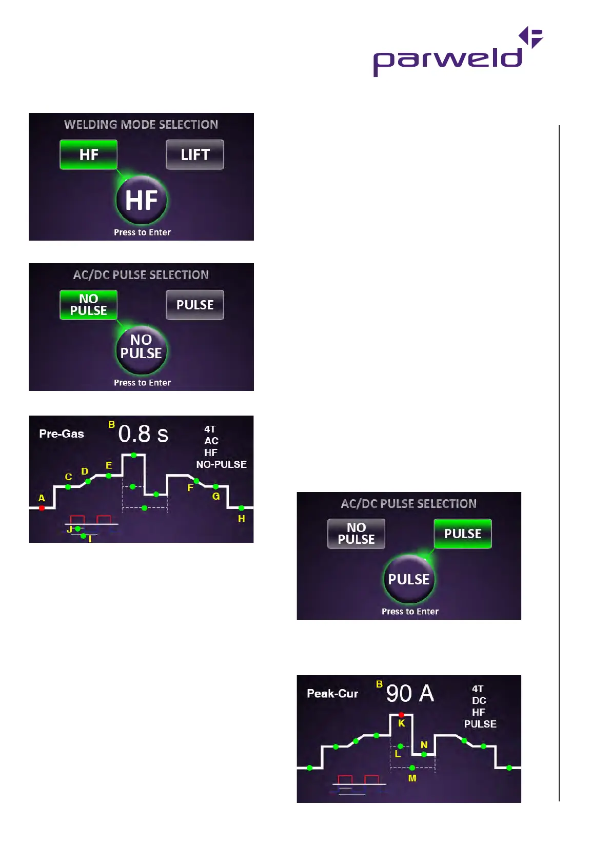
6) Select HF start.
7) Select No Pulse.
8) Rotate the control knob to move the illuminated LED to the gas
pre-flow position (A).
9) Press the control knob to select the parameter. The red LED will
now flash. Adjust the value by rotating the control knob. This can
be adjusted from 0.1 to 0.3 seconds. The value is displayed on the
digital display (B) Press the control knob again to accept the setting.
10) Rotate the control knob to move the LED to the initial current (C)
This can be adjusted from 5 to 100% of the main welding current.
The value is displayed on the digital display (B). 50% is a good initial
setting. Note this function only operates in 4T switch mode.
11) Rotate the control knob to move the LED to the slope up time (D)
This can be adjusted from 0 to 10s. The value is displayed on the
digital display (B). 2s is a good initial setting.
12) Rotate the control knob to move the LED to the main welding
current (E) This can be adjusted from 5 to 200A. The value is
displayed on the digital (B). Refer to the TIG welding guide for a
recommended welding current.
13) Rotate the control knob to move the LED to the slope down time
(F) This can be adjusted from 0 to 10s. The value is displayed on the
digital display (B). 2s is a good initial setting.
14) Rotate the control knob to move the LED to the final current (G)
This can be adjusted from 5 to 100% of the main welding current.
The value is displayed on the digital display (B). 10% is a good initial
setting. Note this function only operates in 4T switch mode.
15) Rotate the control knob to move the LED to the Post Gas time
(H). This can be adjusted from 0.1 to 10s. The value is displayed on
the digital display (B). 3s is a good initial setting.
16) Rotate the control knob to move the LED to the AC frequency (I)
This can be adjusted from 25 to 200Hz dependant on the welding
amperage. The value is displayed on the digital display (B). 60hz
is a good initial setting. Increaseing the frequency has the effect of
stiffening and focussing the arc making it good for welding close to
threads or for crater filling.
Note the maximum frequency available depends upon the welding
amperage selected.
<50A 50 to 250Hz
50-100A 50-200Hz
100-150A Max 150Hz
150-200A Max 100Hz
17) Rotate the control knob to move the LED to the AC balance (J)
This can be adjusted from 15 to 50% . The value is displayed on
the digital display (B). 15% is a good initial setting. Increasing the
percentage has the effect of increasing the time the arc spends in
the electrode positive state which gives a greater cleaning effect on
the material but will reduce weld speed. For good clean material you
should be able to keep the cleaning percentage set at 15 to 20%
You are now ready to weld. The above settings are a guide and you
should adjust to suit the job you are welding. If you are unfamiliar
with the machine try to adjust only one parameter at a time so you
become familiar with its effect.
7.7.7 TIG welding (With Pulse)
It is possible to use the pulse function with both AC and DC TIG
welding. Power Pulsing can give significant advantages on thinner
material to control heat and penetration.
1) Follow the setup as previously described for AC or DC TIG
welding. At the Pulse Selection menu select Pulse.
3) Press the control knob to move the LED to the Peak current
(K) This can be adjusted from 5 to 200A (10-200A for AC welding)
dependant on the welding amperage. The value is displayed on the
digital display (B). Peak current is the maximum amperage that will
be output.


 To Next Page