www.parweld.com
66
3.0 Technical
Specications
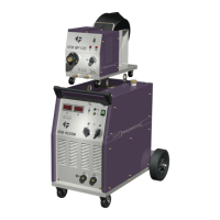
The XTM 221Di, is a compact type machine with integrated wire feed
unit for use with single phase 110/230V supply with smart
input switching.
Process Feature XTM 221Di
Input Voltage 110V+/10% 230V+/-10%
Hz
50/60
Phases
1
KVA
3.7
Generator Size
7 KVA
No-load Voltage (V)
45V
Wire Drive
4 Roll
Fuse Rating (A)
32 16
IP Rating
IP23S
Weight (Kg)
27.8
MIG
DC Input Current (A)
35.5 26.2
DC Input eective
Current (A)
19.4 14.4
DC Welding Current (A)
10~140 10~200
Welding Voltage (V)
14.5~21 14.5~24
TIG
DC Input Current (A)
32.2 25.0
DC Input eective
Current (A)
17.7 12.5
AC Input Current (A)
31.9 25.7
AC Input eective
Current (A)
17.5 14.1
DC Welding Current (A)
10~140 10~200
AC Welding Current (A)
10~140 10~200
Welding Voltage (V)
10.4~15.6 10.4~18.8
MMA
DC Input Current (A)
30.8 29.7
DC Input eective
Current (A)
21.8 16.2
AC Input Current (A)
33.8 32.2
AC Input eective
Current (A)
20.0 16.1
DC Welding Current (A)
10~110 10~200
AC Welding Current (A)
10~110 10~200
Welding Voltage (V)
20.4~24.4 20.4~28
Plasma
DC Input Current (A)
49.1 29.2
Input eective (A)
21.9 16.0
Load Voltage
140V 140V
No load Voltage
226V 226V
DC Output Current (A)
15-25 15-40
4.0 Installation
Read entire installation section before starting installation.
SAFETY PRECAUTIONS
• ELECTRIC SHOCK can kill.
• Only qualied personnel should perform this installation.
• Only personnel that have read and understood the Operating
Manual should install and operate this equipment.
• Machine must be grounded per any national, local or other
applicable electrical regulations.
• The MIG power switch is to be in the OFF position when
installing work cable and torch and when connecting other
equipment.
4.1 Location
Position the power source so that its cooling air inlets and outlets are
not obstructed.
A. 100mm (4in.) minimum
B. 100mm (4in.) minimum
B
A
Duty Cycle (DC)
110V input 230V input
MIG
30% 60% 100% 30% 60% 100%
140A 100A 75A 200A 140A 110A
TIG
30% 60% 100% 25% 60% 100%
140A 100A 75A 200A 130A 100A
MMA
50% 60% 100% 30% 60% 100%
110A 100A 80A 200A 140A 110A
Plasma
20% 30% 60% 100%
25A 40A 28A 22A
Duty Cycle (AC)
110V input 230V input
TIG
30% 60% 100% 30% 60% 100%
140A 100A 75A 200A 140A 110A
MMA
30% 60% 100% 25% 60% 100%
110A 80A 60A 200A 130A 100A