Fatigue Technology Inc. 401 Andover Park East Seattle, WA • USA 98188-7605 Tel: (206)246-2010 Fax: (206)244-9886
358856-REV K 7
10. If hoses require replacement, contact the FTI Sales Department.
SECTION 3.0: PULLER UNIT OPERATING INSTRUCTIONS
Become familiar with these instructions before operating the puller.
3.1 PULLER UNIT SETUP PROCEDURE
Refer to Section 6.0 (Illustrated Parts Breakdown) for parts identification.
1. Ensure that the PowerPak is NOT connected to the air supply. If needed, disconnect the PowerPak
from the air supply, following the appropriate operator manual for the pump model being used.
2. Uncoil the hose assembly of the puller unit, and inspect all threads, couplings, and hoses for damage and
degradation.
3. If the chuck assembly/adapter (see Figure 6.1-1, Item Number 17) needs to change, remove the front
barrel by loosening the barrel lockring (Item Number 8) with the provided spanner wrench (Item Number
30), followed by the barrel (Item Number 3). Thread on the appropriate adapter, then reattach the barrel
and lockring.
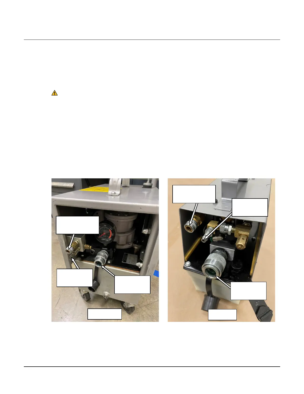
4. Identify the connection ports on the FTI PowerPak where the puller unit hoses will go. See Figure 3.1-1
below.
Figure 3.1-1
PowerPak Connection Ports
Air Pressure
Port
Port
Port
Air Signal
Port
Air Pressure
Port
Air Signal
Port