Fatigue Technology Inc. 401 Andover Park East Seattle, WA • USA 98188-2868 Tel: (206)246-2010 Fax: (206)244-9886
8 358856-REV K
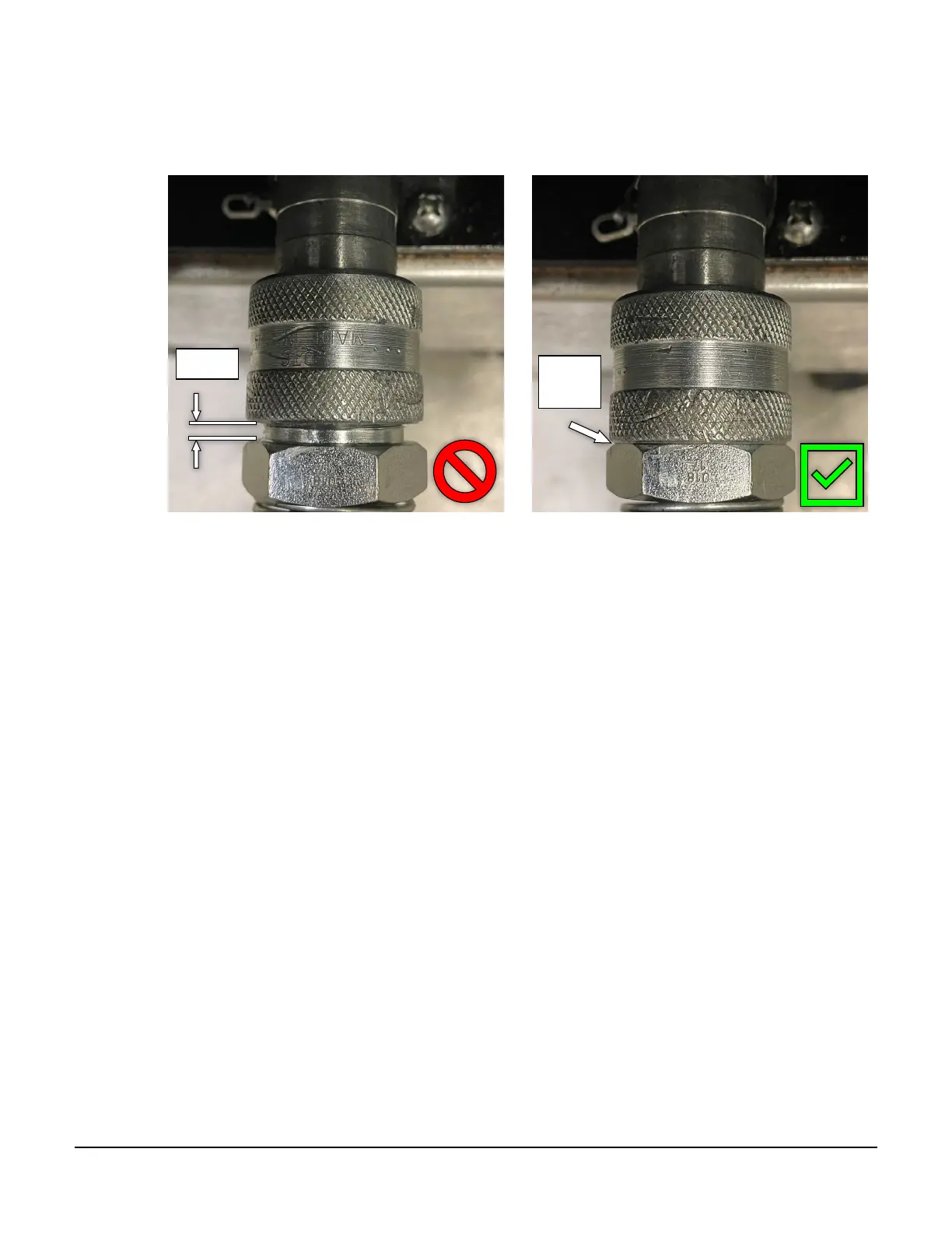
5. Remove protective caps from the hydraulic fittings and thread the hydraulic hose fitting from the puller
unit (male) onto the hydraulic fitting of the FTI PowerPak (female). Wipe fittings clean prior to
connecting. Make sure to thread couplers completely together, with no gap visible. See Figure 3.1-2
below.
Figure 3.1-2
Hydraulic Coupler Connection
6. Connect the male/female air quick-disconnects from the puller unit to the FTI PowerPak.
7. Install the appropriate mandrel into the threaded adapter (hand tight).
8. Install the appropriate nosecap assembly over the mandrel and thread onto the barrel (hand tight).
9. Connect the PowerPak to the air supply, following the appropriate operator manual for the pump model
being used.
3.2 ACTUATION OF THE PULLER
1. The puller unit can be activated only when connected to an FTI PowerPak.
2. Activate the puller unit by depressing the trigger on the handle. Hydraulic pressure is transmitted through
the hose to the cylinder of the puller unit which then retracts the hydraulic piston.
3. Release the trigger once the mandrel clears the workpiece. This changes pressure at the pilot valve to stop
the pull cycle and return the puller unit to its original position.
4. If the puller unit fails to operate as detailed above, refer to Section 5.0 (Troubleshooting).
Gap