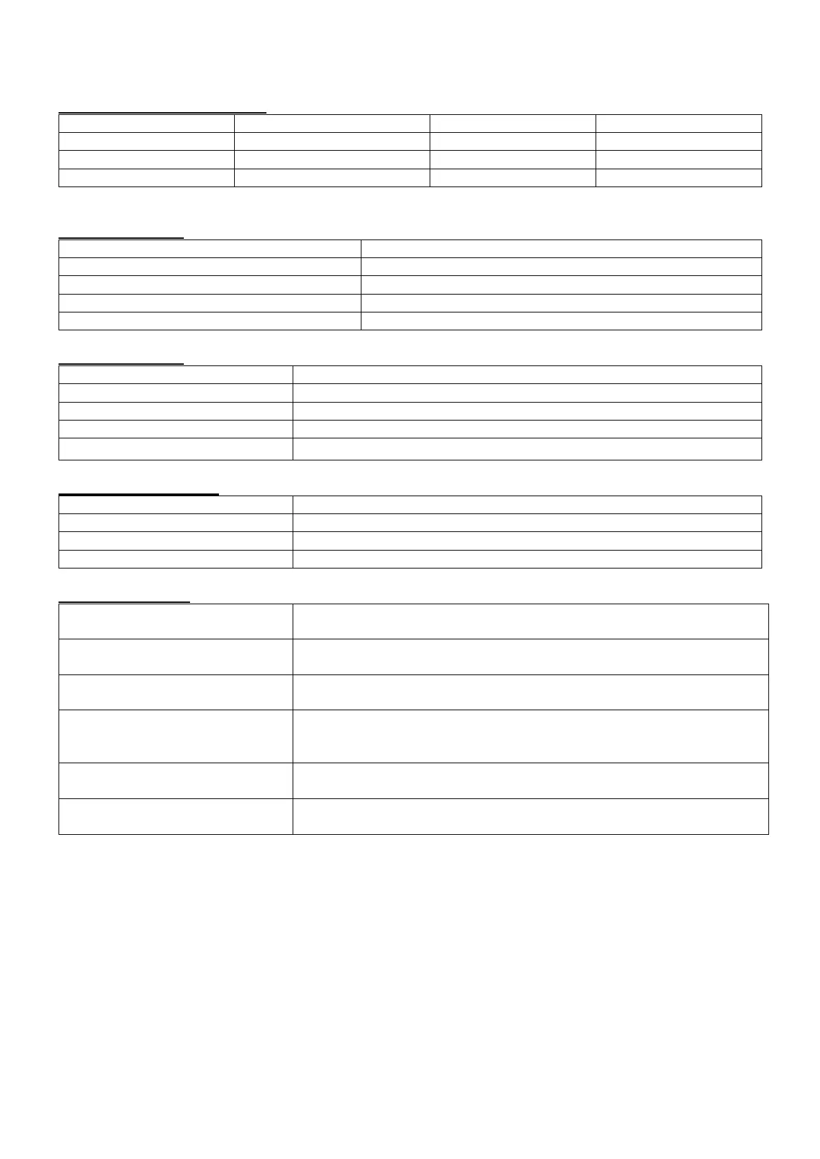
8. Specifications
8.1 Frequency Measurement
Note: measured on Reference Voltage Input A/L1.
8.2 Voltage Input
4 (3 phase + neutral) DC coupling
Max continuous input voltage
8.3 Current Input
4 (3 phase + neutral) DC coupling
Clamp Current Sensor, with mV output
0~±5.625Vpeak, 0~3.97Vrms sinewave
1 to 3000Arms with supplied current clamp
8.4 Sampling System
20kS/s for each channel, 8 channels sample synchronously
5000 points for 10/12 cycles (according to IEC 61000-4-30)
4096 points for 10/12 cycles (according to IEC61000-4-7)
8.5 Display Mode
4 voltages and 4 currents signal waveforms can be displayed
synchronously, displayable under Scope and Transient modes.
Intuitively view voltage and current phases of each phase
(Displayable under Unbalance)
Displayable under voltage/current/frequency, harmonic, power and
energy, flicker, unbalance modes.
Display Trend record of measurement parameters changes over
time (Displayable under voltage/current/frequency, power and
energy, dips and swells, inrush current, flicker, monitoring modes)
Display information of events exceeding limits value (Displayable
under Dips&Swells, Transient, Inrush current, Monitoring modes.)
Harmonic and interharmonic bar graph display mode is more
intuitive (Displayable under harmonics and monitoring modes)
-71-