42
BOILER CONTROL: OPERATION
The next value, Flame Failures, is the number of
times the burner has dropped out due to flame
failure. Several flame failures may have occurred
during the factory firetests and installation. If there
are a large number of flame failures showing on
this screen, contact your Peerless
®
Representative.
On Screens #5 and #6, the Flame Measurement
values 1-4 are logged in the last two seconds of
the most recent ignition sequence in 1/2 second
intervals. This helps service contractors to
diagnose ignition issues.
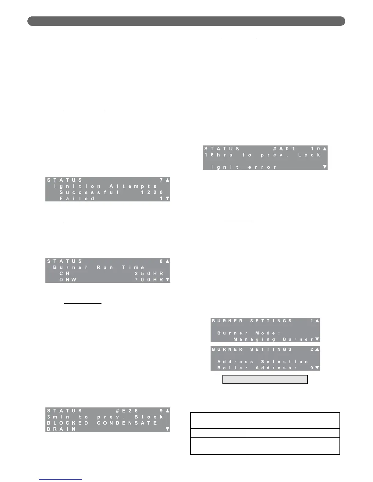
d. Ignition Attempts
: Screen #7 provides information
about ignition attempts. Obviously, the total
ignition attempts are the sum of the successful and
failed attempts. Several ignition failures may occur
during factory firetest and equipment
commissioning. However, if there are a large
number of failed ignition attempt showing on this
screen, contact your Peerless
®
Representative. If
there is an unusually large number of total ignition
attempts, there may be a problem with the boiler
short cycling.
e. Burner Run Time
: Screen #8 provides
information about the total run time of each
burner. The total burner run time is the sum of the
central heating (CH) and domestic hot water
(DHW) hours. The total boiler run time is the sum
of both burner run times.
f. Blocking Errors:
Screen #9 provides error history
about the last 16 blocking errors. Blocking errors
are errors that prevent the burner from operating
until the condition causing the error is corrected.
Sensor errors, low water, and blocked vent are
examples of this type of error. To review previous
errors, press the select key. The number in the
upper right changes from the status screen “9” to
a blinking “0” indicating that this is the most
recent error. Use the arrow keys to scroll through
previous errors from 0 to 15. If the screen shows
“#255” in the error number location, this
indicates that there is no error stored in this
location. All errors on screens higher than one
showing “#255” should also indicate no error.
Table 10.1 (in Section 10) provides a list of
blocking errors.
g. Lockout Errors:
Screen #10 provides error history
about the last 15 locking errors. Locking errors are
errors that require a manual reset on the control
board (pushing the “Reset” key on the display) to
reset the burner once the condition causing the
error has been corrected. Ignition Failure, Flame
Failure and High Limit Temperature are examples
of this type of error. To review previous errors,
press the “Select” key. The number in the upper
right changes from the status screen number “10”
to a blinking “0” indicating that the screen is
showing the most recent lockout error. If the
burner is not in lockout, this position should show
“#255” in the error number location. Use the
arrow keys to scroll through previous errors from 1
to 15. As with blocking errors, “#255” always
indicates that no error is stored in this location.
Table 10.2 provides a list of lock out errors.
3. Burner Settings
The burner settings menu allows the installation or
service contractor to change settings which effect the
burner operation. The following are descriptions of
the available settings.
a. Burner Mode
: The burner modes are set by
default from the factory. The upper burner, which
corresponds to the display closest to the front of
the boiler, is always the “managing burner”. The
lower burner, with its display toward the rear, is
always the “dependent burner”. These values are
not intended to be changed in the field.
b. Boiler Address
: The PUREFIRE
®
PF-850 & PF-1000
can be operated with as many as 15 identical
boilers as a cascade boiler system by adding 2
wire communication links between the boilers.
The following chart shows the role of the boiler
depending on the boiler address. Multiple boiler
operation is covered in-depth at the end of this
section of the manual. This screen is available
only on the managing burner.
Figure 8.17: Status – Ignition
Figure 8.18: Status – Burner Run Time
Figure 8.19: Status – Blocking Errors
Figure 8.20: Status – Locking Errors
Figure 8.21: Burner Settings – Burner Mode &
Boiler Address
Table 8.7: Boiler Address
Boiler Address
Value
Description
0 Stand-Alone Boiler
1 Master Boiler in a Cascade System
2-16 Dependent Boilers in a Cascade System
Managing Burner Only