43
BOILER CONTROL: OPERATION
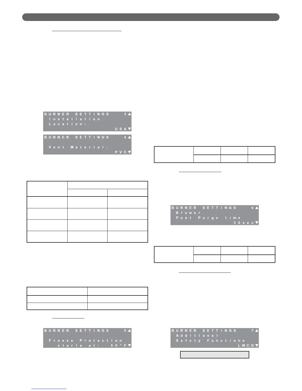
c. Installation Location & Vent Material: Due to
differing national codes in the United States and
Canada, there are different material requirements
for exhaust vent pipe. Therefore, the maximum
vent limit temperature is different depending on
the material used.
Screens #3 and #4 allow the installer to select the
installation location and vent material. Based on
the information given, Table 8.8 shows the
exhaust temperature that the control will allow
before reducing the burner input rate. If the
temperature of the exhaust gas approaches these
values, the control will reduce the input rate on
both burners until the temperature begins to drop.
If the flue temperature continues to rise, the
control will shut down both burners.
Note: Although stainless steel can withstand a
temperature higher than 230°F (110°C) the
temperature limit is set to this temperature since
the vent temperature should not exceed this
temperature unless there is a problem with the
heat exchanger.
d. Freeze Protection
: Freeze protection is intended to
prevent freezing the central heating system.
•
First, the control activates pumps to distribute
heat uniformly through the system.
– If the boiler supply (header) temperature
drops below the value selected for “Freeze
Protection starts at:”, the General (boiler)
circulator is activated.
– If either of the boiler return sensors reports a
value below this temperature, the CH
circulator is started.
•
Next, if Burner M return temperature drops more
than 9°F (5°C) below the “Freeze Protection
starts at:” value, the control activates Burner M
(managing burner) at it minimum rate.
– If a central heat demand is detected while the
burner is operating for Freeze Protection, the
burner will run normally to satisfy the demand.
– Finally, once the return temperature
increases to 9°F (5°C) above the chosen
value, the burner is switched off and the
pumps are deactivated.
e. Blower Postpurge Time
: The blower postpurge time
can be increased to address problems under extreme
conditions (long exhaust vent runs, high winds, etc.)
where the products of combustion are not fully
expelled from the venting system. This feature
should be used sparingly as it may lead to decreased
efficiency and higher fuel bills in certain situations.
f. Additional Safety Functions
: This feature allows
the installer to choose between using a low water
cut-off or a flow switch to assure proper water
circulation and operation of the boiler. Either of
these devices should be wired to the terminals 11
& 12 (Safety Interlocks) of the P
UREFIRE
®
PF-850
or PF-1000 boilers. Note that these terminals are
connected internally to the high & low gas
pressure switches so that a “Safety Interlock Open”
error may occur due to high or low gas pressure in
addition to anything connected to these terminals.
Figure 8.25: Burner Settings – Additional Safety
Functions
Figure 8.24: Burner Settings – Blower Post Purge
Table 8.10: Freeze Protection Range & Default
Table 8.11: Blower Post Purge Range & Default
Table 8.8: Vent Temperature Limits
Vent Material
Location
U.S.A. Canada
PVC
190°F
(80°C)
149°F
(65°C)
CPVC
230°F
(110°C)
190°F
(80°C)
Polypropylene
(PPs)
230°F
(110°C)
230°F
(110°C)
Stainless Steel
230°F
(110°C)
230°F
(110°C)
Freeze Protection
Starts at
Default Minimum Maximum
50°F (10°C) 45°F (7°C) 56°F (13°C)
Blower Post
Purge Time
Default Minimum Maximum
30 sec 30 sec 120 sec
Table 8.9: Location & Vent Material Default
Figure 8.23: Burner Settings – Freeze Protection
Parameter Default
Location U.S.A.
Vent Material PVC
Figure 8.22: Burner Settings – Location & Vent
Material
Managing Burner Only