44
BOILER CONTROL: OPERATION
•
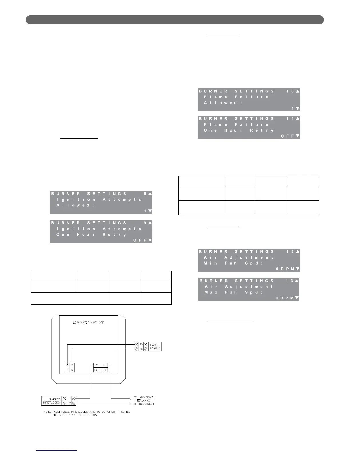
LowWaterCO: This is the default selection on the
control. However, no low water cut-off (LWCO)
device is supplied with the boiler. A probe-type
LWCO, such as the Hydrolevel Model 1150 or
McDonnell & Miller RB-120 should be used with
P
UREFIRE
®
boilers. Figure 8.27 shows the
recommended wiring of these devices.
•
FlowSwitch: A flow switch, such as the
McDonnell & Miller FS250, is designed to
trigger a blocking error immediately on a loss
of flow in the system. To protect from a false
flow reading on this type of device, the control
assures that the flow switch is open (indicating
no flow) before activating the General and the
CH or DHW circulator. After these pumps are
activated, it will not proceed into a trial for
ignition until the switch closes.
g. Ignition Attempts
: The control is configured from
the factory to not allow the burner to recycle after
a failed ignition attempt. At installation, the control
can be configured to allow up to 3 ignition
attempts before locking out and requiring a
manual reset. In addition, the control may be
configured to retry for ignition, one hour after
lockout without a manual reset. Check applicable
codes before changing these parameters.
h. Flame Failures
: The control is configured from the
factory to not allow the burner to recycle after a
flame failure. At installation, the control can be
configured to allow up to 2 retries after a flame
failure before locking out and requiring a manual
control reset. In addition, the control may be
configured to retry for ignition one hour after a
lockout without a manual reset. Check applicable
codes before changing these parameters.
i. Air Adjustment
: Screens #12 and #13 allow the
fan speed to be increased if required. The
following is an explanation of the conditions under
which these adjustments should be made.
j. Minimum Fan Speed
: The minimum fan speed
adjustment is intended to respond to potential
issues with the loss of flame due to pressure
fluctuations in the venting system. These concerns
may be due to wind gusts on sidewall vented
boilers or other sources of exhaust vent pressure
spikes. The minimum fan speed may be adjusted
in 30 RPM increments up to the minimum fan
speed + 540 RPM. This feature should only be
used to address nuisance flame failure or flapper
valve failure lockout errors.
Figure 8.27: Low Water Cut-off (LWCO) Wiring
Figure 8.28: Burner Settings – Flame Failures
Allowed
Figure 8.26: Burner Settings – Ignition Attempts
Allowed
Table 8.12: Ignition Attempts Ranges & Defaults
Table 8.13: Flame Failures Allowed Ranges &
Defaults
Parameter Default Minimum Maximum
Ignition Attempts
Allowed
1 1 3
Ignition Attempts
1 Hr Retry
OFF OFF ON
Parameter Default Minimum Maximum
Flame Failure
Retries Allowed
0 0 2
Flame Failure
1 Hr Retry
OFF OFF ON
Figure 8.29: Burner Settings – Air Adjustment