Date of issue 11/30/07 805639
HART Loop Converter KFD2-HLC-(Ex)1.D(.**)
Installation and connection
12
5.3 Setting parameters of HART field device
In order to set the parameters of the connected HART field device, you will require a HART handheld
terminal which you can connect to terminals 22/24 or the field cables. Transmitting the HART signal
via the current outputs of the HLC is not possible.
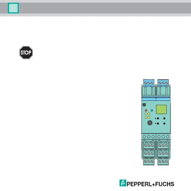
5.4 Front
The following are located on the front of the HLC:
• a display for showing the measured values, the current output values
and fault messages and for displaying in parameterization mode
• four keys for selecting the displayed values/current output value and for
setting the parameters of the HLC:
S (Up) T (Down) ESC (Escape) OK
• RS 232 serial interface for a connection to a PC for setting parameters
and diagnosis of the HLC using PACTware
TM
(available from 2009)
• LED ERR (red) to indicate a fault
• LED PWR (green) to indicate the presence of the supply voltage
also for KFD2-HLC-(Ex)1.D.2W and KFD2-HLC-(Ex)1.D.4S:
• LED OUT 1 (yellow) to indicate that relay 1 is active
• LED OUT 2 (yellow) to indicate that relay 2 is active
also for KFD2-HLC-(Ex)1.D.4S:
• LED OUT 3 (yellow) to indicate that relay 3 is active
• LED OUT 4 (yellow) to indicate that relay 4 is active
When connecting the field cables, use an old handheld terminal if the field cables lead
through a hazardous area.
Warning
10 11 12
16 17 18
456
22 23 24
ESC
OK
789
13 14 15
123
19 20 21
RS232
CH
IN /
K
OUT
43
1
PWR
21
KFD2-HLC-
Ex1.D.4S