For more information on DEF, refer this Operation and
Maintenance Manual, “Fluid Recommendations”.
Engine Specifications
Note: The front end of the engine is opposite the
flywheel end of the engine. The left and the right
sides of the engine are determined from the flywheel
end. The number 1 cylinder is the front cylinder.
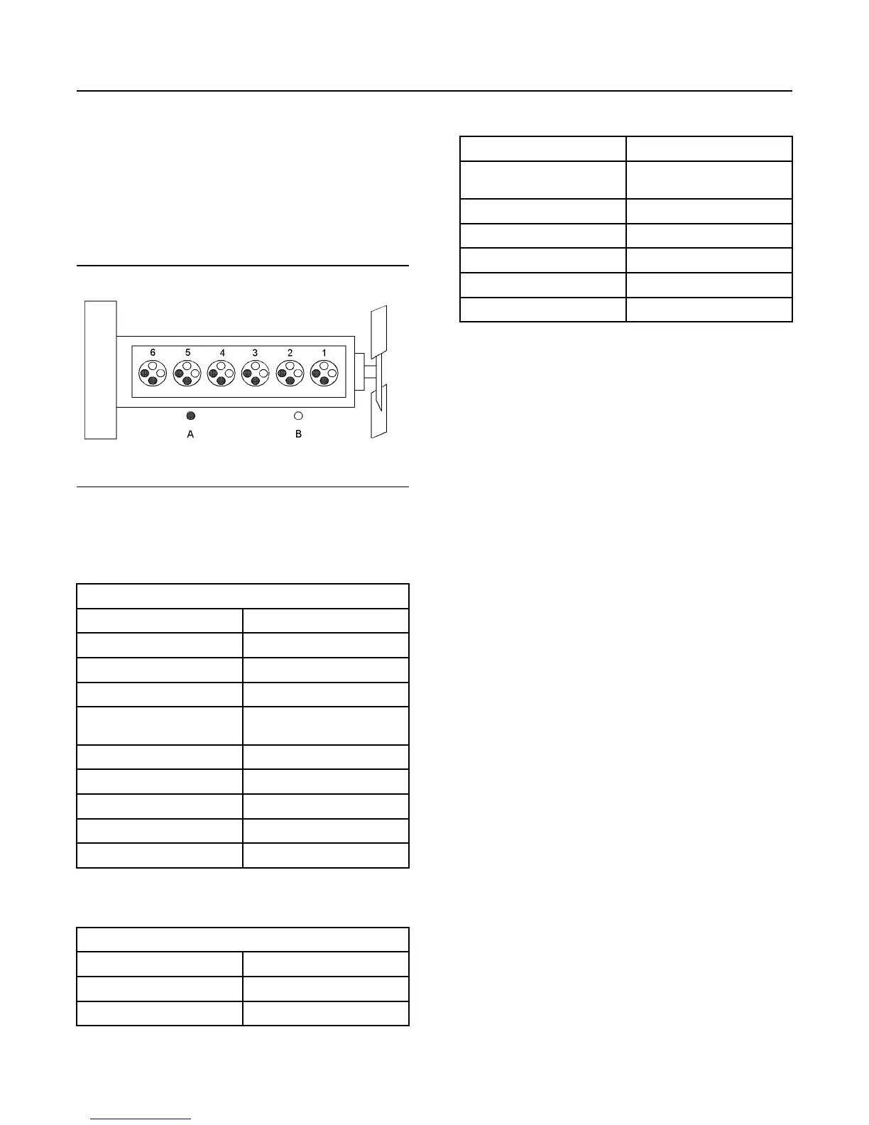
Illustration 22 g01127295
Cylinder and valve location
(A) Exhaust valves
(B) Inlet valves
Table 1
1206F-TA Single Turbocharged Engine Specifications
Operating Range (rpm)
900 to 2800
(1)
Number of Cylinders
6 In-Line
Bore 105 mm (4.13 inch)
Stroke 127 mm (5 inch)
Power
116 to 151 kW
(155.5 to 202.5 hp)
Aspiration Turbocharged charge cooled
Compression Ratio
16.4:1
Displacement 7.01 L (428 in
3
)
Firing Order
1-5-3-6-2-4
Rotation (flywheel end)
Counterclockwise
(1)
The operating rpm is dependent on the engine rating, the appli-
cation, and the configuration of the throttle.
Table 2
1206F-70TTA Series Turbocharged Engine Specifications
Operating Range (rpm)
900 to 2800
(1)
Number of Cylinders
6 In-Line
Bore 105 mm (4.13 inch)
(continued)
(Table 2, contd)
Stroke 135 mm (5.31495 inch)
Power
151 to 205 kW
(202.5 to 274.9 hp)
Aspiration Turbocharged charge cooled
Compression Ratio
16.4:1
Displacement 7.01 L (428 in
3
)
Firing Order
1-5-3-6-2-4
Rotation (flywheel end)
Counterclockwise
(1)
The operating rpm is dependent on the engine rating, the appli-
cation, and the configuration of the throttle.
Electronic Engine Features
The engine and aftertreatment operating conditions
are monitored. The Electronic Control Module (ECM)
controls the response of the engine to these
conditions and to the demands of the operator. These
conditions and operator demands determine the
precise control of fuel injection by the ECM. The
electronic engine control system provides the
following features:
• Engine monitoring
• Engine speed governing
• Control of the injection pressure
• Cold start strategy
• Automatic air/fuel ratio control
• Torque rise shaping
• Injection timing control
• System diagnostics
• NOx reduction system control
• Aftertreatment system control
The ECM provides an electronic governor that
controls the injector output in order to maintain the
desired engine speed.
For more information on electronic engine features,
refer to the Operation and Maintenance Manual,
“Features and Controls” topic (Operation Section).
Engine Diagnostics
The engine has built-in diagnostics in order to ensure
that the engine systems are functioning correctly. The
operator will be alerted to the condition by a “Stop or
Warning” lamp. Under certain conditions, the engine
horsepower and the vehicle speed may be limited.
The electronic service tool may be used to display the
diagnostic codes.
SEBU8732 27
General Information
Product Description