3
Workshop Manual, TPD 1458E, issue 3 - Perkins Confidential: Green 27
400 Series
Cylinder head to valve stem clearance
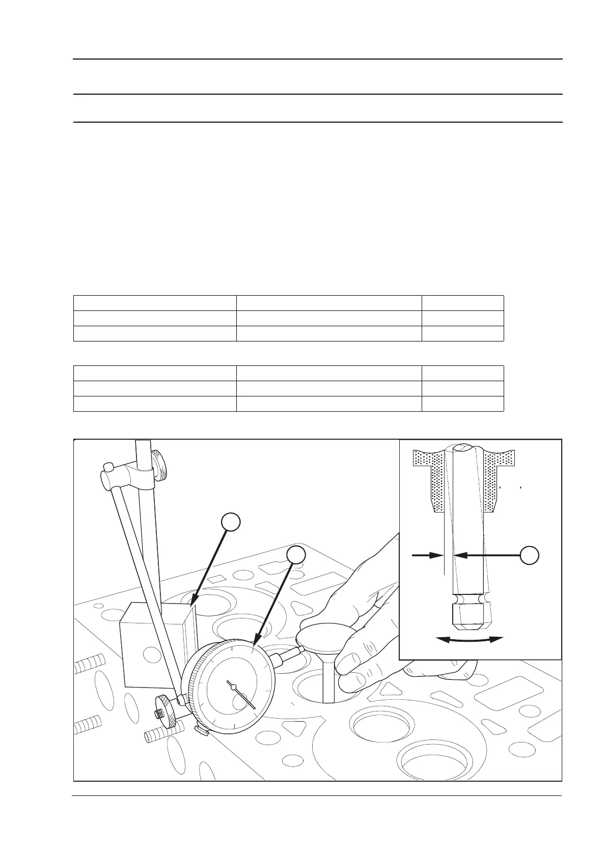
To inspect Operation 3-15
Check the clearance (3) between the valve stem and the cylinder head. If the clearance is greater than the
service limit, the valves must be checked for wear, see Operation 3-14, If the valves are within service limits,
renew the cylinder head.
1 Put a new valve in the valve guide.
2 Put a dial test indicator with a magnetic base (1) onto the face of the cylinder head.
3 With the valve lifted 15,0 mm (0.6 in) and the gauge (2) in contact with the edge of the valve head, move the
valve radially away from the gauge. With the head in this position, set the gauge to ‘0’.
4 Move the valve radially across the axis of the cylinder head towards the gauge. Make a note of the reading
on the gauge if the reading is greater than the service limit, renew the cylinder head.
Maximum permissible clearances with a valve lift of 15 mm (0.6 in).
Inlet valve
Exhaust valve
Engine Clearance mm (in) standard Service limit
403C-11 0,025 - 0,052 (0.0010 - 0.0020) 0,2 (0.008)
403C-15, 404C-22 and 404C-22T 0,030 - 0,060 (0.0012 - 0.0024) 0,2 (0.008)
Engine Clearance mm (in) standard Service limit
403C-11 0,045 - 0,072 (0.0020 - 0.0030) 0,25 (0.010)
403C-15, 404C-22 and 404C-22T 0,050 - 0,075 (0.0020 - 0.0030) 0,25 (0.010)
3
1
2
H1048
 Loading...