KENR9126 119
Troubleshooting Section
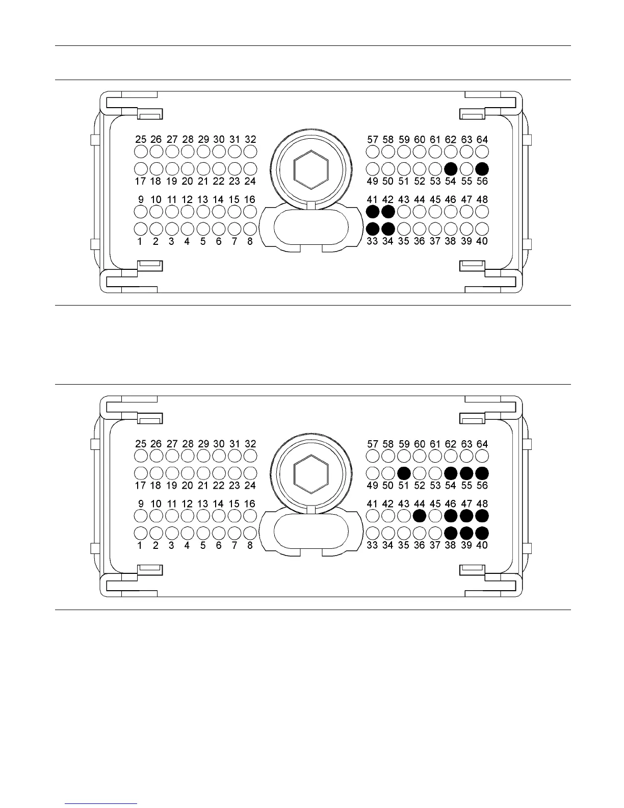
g02199236
Illustration 23
Typical example of the P1 p re ss u re sensor p in lo cat io ns
(33) Voltage supply (5 V) Fuel P ressure
Sensor
(34) Voltage supply (5 V) Exhaust G as
Temperature Sensor
(41) G round (GND) Fuel Pressure Sensor
(42) G round (GND) Exhaust G as
Temper ature Sensor
(54) S ignal (SIG) Exhaust Gas Temperature
Sensor
(56) S ignal (SIG) Fuel Pressure S ensor
g02193219
Illustration 24
Typ
ical exam ple of the P 2 pressure sensor pin locations
(38) Ground (GND) Intake Manifold Pr essure
Sensor
(39) Ground (GND) Oil Pressure Sensor
(40) Ground (GND) Fuel Rail Pressure
Sensor
(44) Gr ound (GND) Transmission O il
Pressure Sensor
(46) Voltage supply (5 V) Intake Manifold
Pressure Sensor and Oil Pressure
Sensor
(47) Voltage supply (5 V) Transmission Oil
Pressure Sensor
(48) Voltage supply (5 V ) Fuel Rail Pressure
Sensor
(51) Signal (SIG) Fuel Rail Pressure Sensor
(54) Signal (S IG) Transmission O il Pressure
Sensor
(55) Signal (SIG) Intake Manifold Pressure
Sensor
(56) S ignal (SIG) O il Pr essure Sens or
Test Step 1. Check for Connector Damage
A
.
T
urn the keyswitch to the OFF position.
B. Check the connectors and the harness for the
following faults:
•
Damage