KENR9126 125
Troubleshooting Section
E. Disconnect the P1 connector.
Note: Wiggle the harness during the following
measurements in order to reveal an intermittent
condition.
F. Measure the resistance between terminals P1-20
(CAN d ata lin
k +) and P1-21 (CAN data link -).
Expected Result:
The resistance is between 57 and 63 Ohms.
Results:
•
OK – The resistance is between 57 and 63 Ohms.
Proceed to
Test Step 5.
•
Not OK – The resistance is between 114 Ohms
and 126 Ohm
s. A termination resistor is missing.
Repair: Verify that two te rmination resistors are
connecte
d to the data link. One resistor must be
located on each end of the data link. The engine
is shipped with one termination resistor that is
installe
d between the ECM and the customer
connector.
Refer to
the appropriate electrical schematic in
order to determine the missing resistor. Replace
the missing resistor. Verify that the problem is
resolve
d.
STOP.
•
NotOK –Theresistanceislessthan57Ohms.
Proceed to Test Step 3.
•
Not OK – The resistance is greater than 126
Ohms. Proceed to Test Step 4.
Test Step 3. Check for a Short Circuit
A. Remo
ve both termination resistors from the CAN
data link.
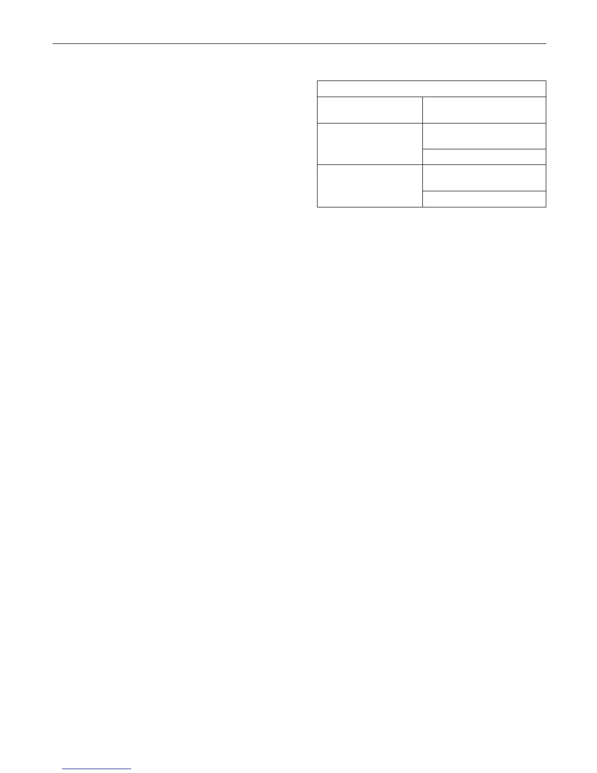
B. Meas
ure the resistance between the points that
arelistedinTable31.Besuretowigglethewires
in the harnesses as you make each resistance
mea
surement.
Table 31
Resistance Measurements for the CAN Data Link
Connector and
Terminal
Terminal
All of the other terminals on
the P1 c onnector
P1-20(CANdatalink+)
Engine ground
All of the other terminals on
the P1 c onnector
P1-21(CANdatalink-)
Engine gro
und
Expected R
esult:
Each check of the resistance indicates an open
circuit.
Results:
•
OK – Each check of the resistance indicates an
open circuit. Proceed to Test Step 4.
•
Not OK – At least one check of the resistance
does not indicate an open circuit. There is a short
circuit
in a harness. There may be a problem with
a connector.
Repair
: Repair the wiring and/or the connector.
Replace part, if necessary. Verify that the problem
is resolved.
STOP.
Test S
tep 4. Check for an O pen Circuit
A. Remove both termination resistors from the CAN
data
link.
B. Fabricate a jumper wire. Use the jumper wire in
orde
r to create a short circuit between terminals A
and B on the tee's connector for the termination
resistor. This will replace the termination resistor
wit
h a short circuit.
C. Measure the resistance between terminals P1-20
(CA
N data link +) and P1-21 (CAN data link -).
D. Remove the jumper wire from the tee. Connect
th
e termination resistors to the data link.
E. Connect the J1/P1 connectors.
Expected Result:
T
he resistance is less than ten Ohms.
Results:
•
OK – The resistance is less than ten Ohms. There
is not an open circuit. Proceed to Test Step 5.