124 KENR9126
Troubleshooting Section
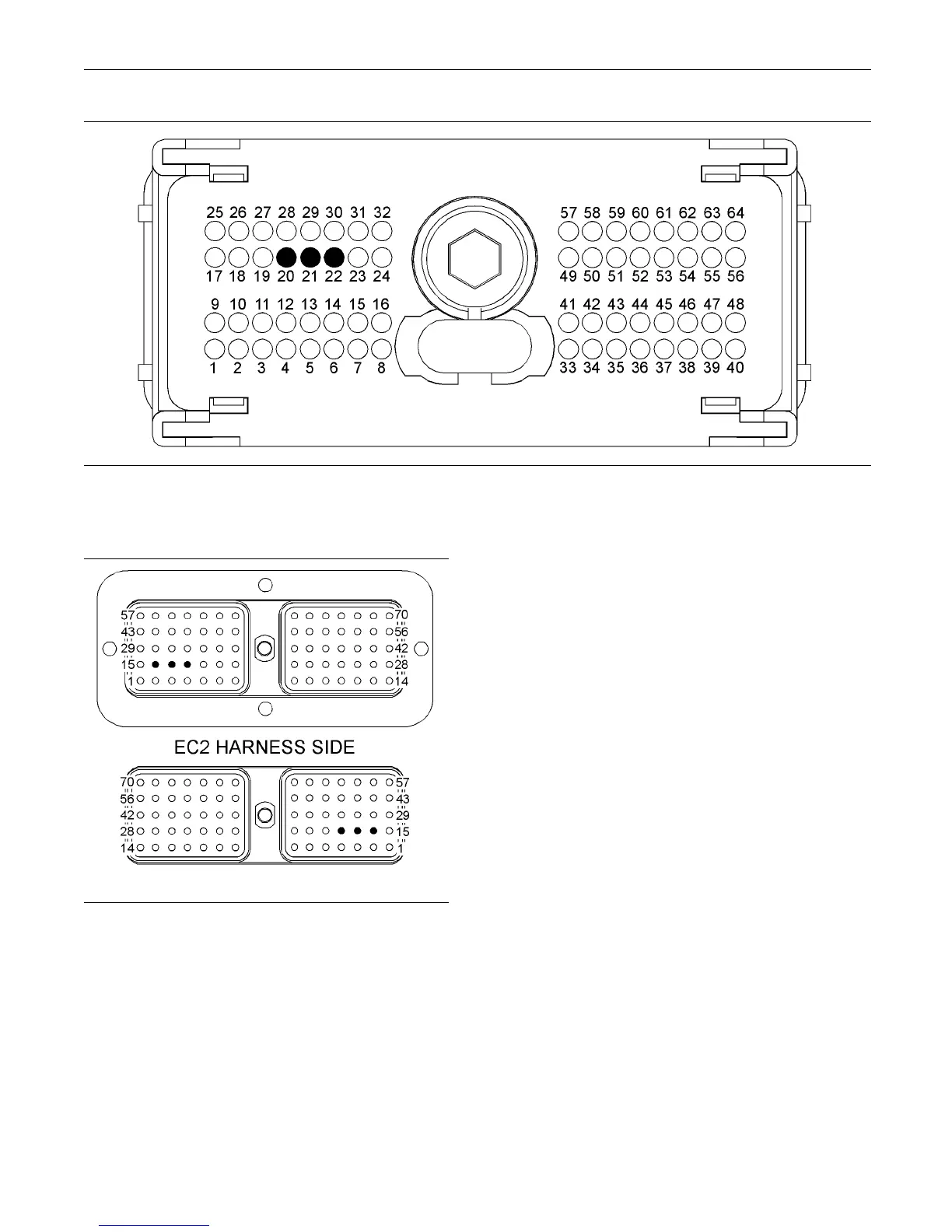
g02193395
Illustration 26
P1 terminals that are associated with the CAN data link
(21) CAN data link − (22) C AN shield (20) CA N data link +
g02199317
Illustration 27
Term inals that are as sociated w ith the C AN data link
(16) Shield
(17) CAN data link +
(18) CAN data link −
C. Perform a 45 N (10 lb) pull test on each of the
wires that are associated with the CAN data link.
D. Check the allen head screw on each ECM
connector and on the customer connector for the
proper torque. Refer to the diagnostic functional
test Troubleshooting, “Electrical Connectors -
Inspect”.
E. Check the wiring harnesses for abrasion, for
corrosion and for pinch points.
Expected Result:
All connectors, pins and sockets are completely
coupled and/or inserted. The harness and wiring are
free of corrosion, of abrasion and of pinch points.
Results:
•
OK – The harness and wiring appear to be OK.
ProceedtoTestStep2.
•
Not OK – There is a problem in the wiring harness.
Repair: Repair the connectors and/or the wiring.
Replace parts, if necessary. Ensure that all of the
seals are properly in place and ensure that the
connectors are completely coupled. Verify that the
problem is resolved.
STOP.
Test Step 2. Verify the P roper Installation
of the Termination Resistors
A. Remove the electrical power from th e ECM.
B. Disconnect the Mini Marine Power Display
(MMPD).
C. Disconnect any other display that is connected to
the CAN data link.
D. Disconnect the electronic service tool from the
service tool connector.