3 Probe Installation
10
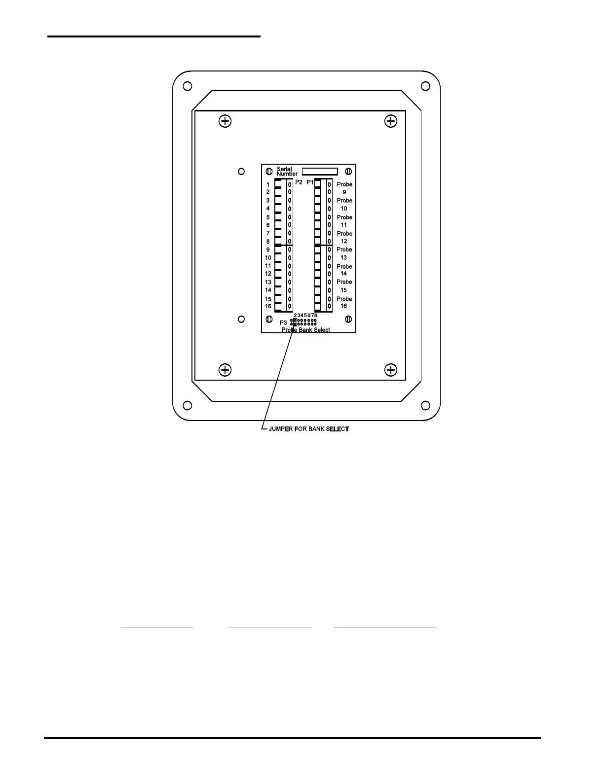
Figure 5
Remote Probe Module
The communication cable runs from P2 on probe bank 1 card in the main enclosure to P2 on the first
RPM-8, then to P2 on the next RPM-8, etc. Normally each RPM-8 is set to a unique probe bank select
number. The maximum distance from a probe to the main alarm panel (including communication cable)
is 20,000 feet using probe wire and communication cable. Figure 6 is a typical field-wiring layout.
The communication cable can branch from one RPM-8 to 2 or 3 RPM-8’s in a star pattern. This may be
convenient if the probes are located in separate areas of a site. The maximum number of
communication cables that can be connected together at terminal strip P2 is 4.
When 2 or more wires are going into the same terminal, it is recommended that a wire crimp ferrule be
used to crimp the wires together. Then a single ferrule is inserted into each terminal pin. This will make
installation easier and reduce field-wiring errors. The following is a guide for crimping 2, 3, or 4 wires
together.
Number of wires Ferrule size (AWG) Crimp tool setting (mm)
2 16* or 14 1.0* or 1.5
3 14 1.5
4 14 1.5
* A #16 AWG ferrule is the largest size allowed connected to P2 on probe bank 1 on Model LW64-IS.
PermAlert recommends using Eclipse Model 300-016 Wire Ferrule Crimp Tool or equivalent, available
from PermAlert.
 Loading...