LiquidWatch Installation Manual
11
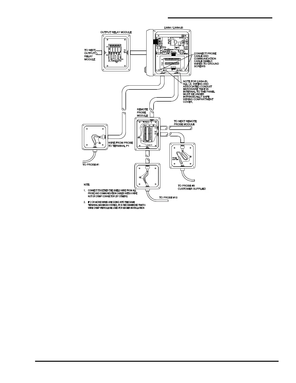
Figure 6
LiquidWatch Field Wiring Diagram
3.3 Probe Installation
1. Each PermAlert supplied probe is furnished with an integral probe adapter. Probe adapters are also
available to connect customer supplied probes to the LiquidWatch monitoring system. A standard 6”
x 6” x 4” junction box can house several probe adapters or several standard probe splices (see
Figures 7 and 8). (PermAlert can supply NEMA 4X junction boxes and cord grips.)
2. Mount a junction box or a remote probe module at a location close to the point being monitored.
PermAlert supplies probes with 20 feet of probe lead cable, but additional lead cable may be used if
necessary.
3. Figures 10 through 13 show typical probe installations. Install the probe and use electrical conduit
and/or watertight cord grips, as necessary, to prevent water entry where the probe lead penetrates
the monitored area. Cord grip part # 8057955 is for the probe lead cable.
4. Once the probe is installed, the probe lead should be routed to the junction box or the remote probe
module. Trim the excess length of the probe lead before splicing it. Splice the leads by using the
crimp connectors supplied with the probe or probe adapter. Make sure the shrink tubing on the
connector covers the insulation of the wires, so no bare copper wire is exposed. Heat the splice with
a heat gun to seal the adhesive-lined shrink tubing on the connector (see Figures 7 and 8).
5. The shields from each communication cable and all probe cables in a junction box must be
connected together at each RPM-8. The shields must be grounded in the alarm panel to one
of the 4 mounting screws for the backplate (see Section 2.2).
 Loading...