LiquidWatch Installation Manual
27
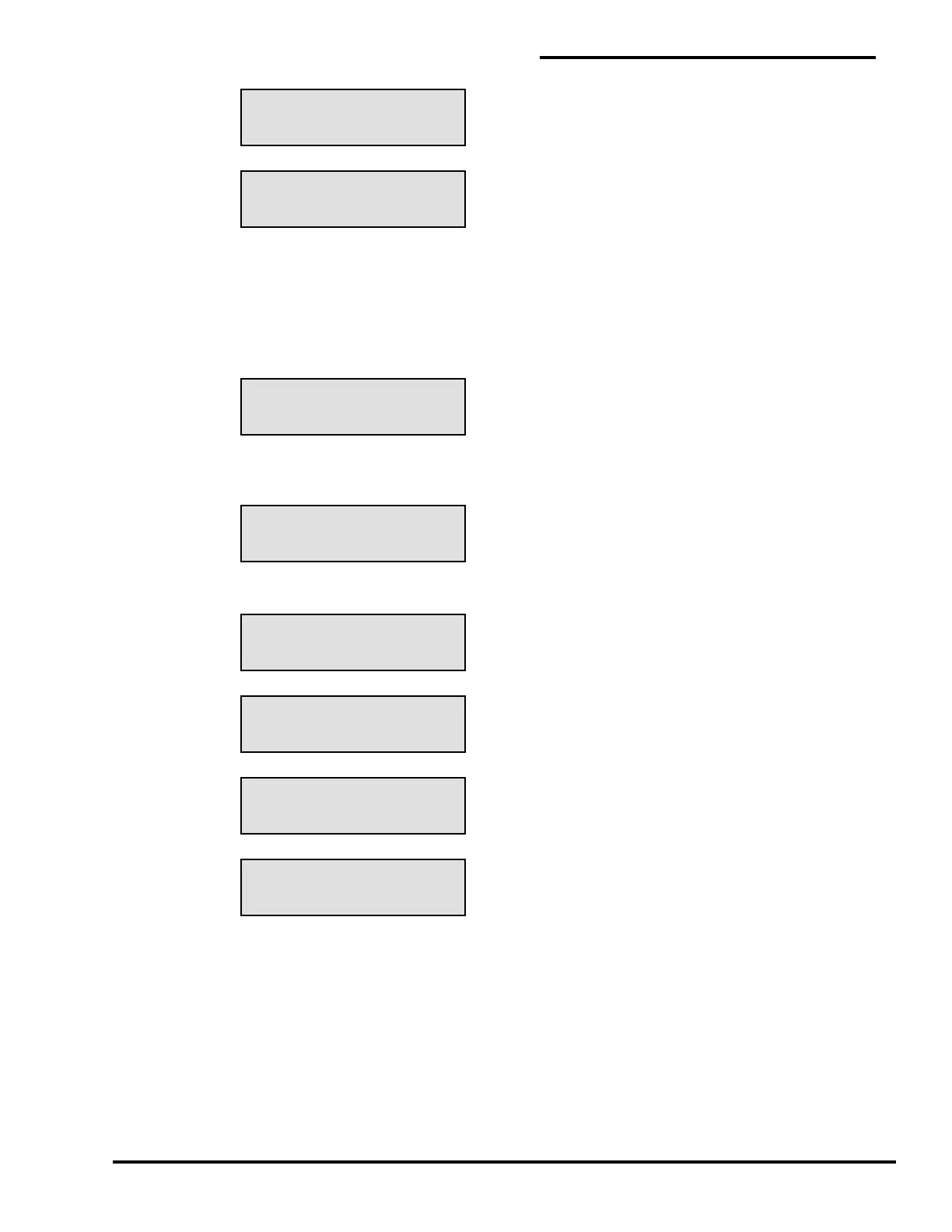
SETUP MENU TYPE
NC CONTACT 3 OF 4
SETUP MENU TYPE
NO CONTACT 4 OF 4
SETUP MENU SELECT
RELAY # 00 OF 04
SETUP MENU TESTING
PROBE # 01 OF 08
SETUP MENU GOOD
PROBE # 01 000
SETUP MENU BREAK
PROBE # 01 000
SETUP MENU ACTIVE
PROBE # 01 000
SETUP MENU SHORT
PROBE # 01 000
Next select which relay is switched when the selected probe is activated if an optional output relay
module(s) is installed. If relay #00 is selected, then no output relays will be assigned to the selected
probe. More than 1 probe can select the same relay. The common alarm relay on the main board is
switched when any probe is activated.
If the maximum number of relays is shown incorrectly (4 in this case) go to Section 5.7.4 and configure
the system. Select the relay and press “Enter”.
At this time LiquidWatch will test the probe to see if it is within acceptable limits for the probe type
selected.
One of the following messages is then displayed:
The number at the end of the second line is between 0 and 254 and is used for diagnostic purposes.
The values may be compared to the table in Section 3.7, “Probe Tests”. A “Break” or “Short” alarm
indicates a problem with the probe lead cable between the panel and the probe adapter on the probe.
An “Active” message indicates the probe is active or the probe lead cable from the probe to the probe
adapter is damaged.
If the shielded probe and communication cables are not properly installed and grounded, the values may
change due to “electrical noise” and cause nuisance alarms. If the ”” key is pressed again at this
point, a new reading will be taken. If the range of values for a probe varies more than ± 5 counts, the
wiring should be rechecked for proper grounding.
Press “Enter” to continue to save the probe setup data and go to the next probe. Then either repeat
these steps for another probe or press “M” to return to the Main Menu.
 Loading...