route wire along the outside wall and bury before cutting.
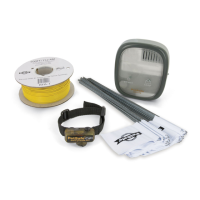
Splice the ends of the white twisted wire to the ends of the
boundary wire with the supplied waterproof splices. Do not
untwist the wire any more than necessary to splice the wires
together.
WARNING: Use only the waterproof splices (approved for
direct burial) supplied with this system. If additional splices
are required, they may be purchased from Invisible Fence at
1-800-688-4364.Using non-waterproof electrical tape, solder,
or twisted wire nuts will cause an intermittent signal or disable
the system.The waterproof splices included in your contain-
ment system are designed to provide a sealed connection
between the wires.
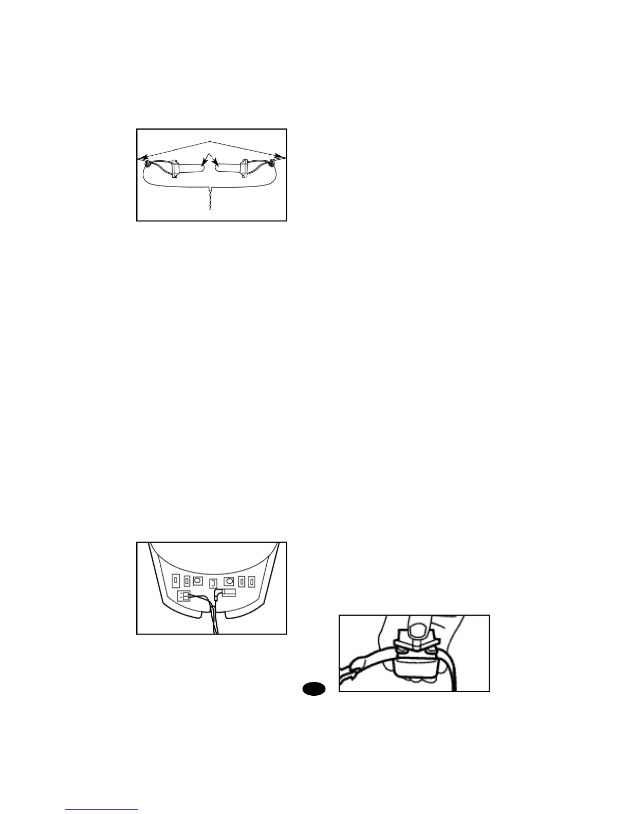
Use the supplied waterproof splices to make proper
connections. To use the splices, strip 5/8” of insulation
from the ends of the wires you are joining.With the ends
of the wires even and together, place the wire nut over
the wire ends and turn the wire nut clockwise until it is
securely fastened.Snap open the hinged lid of the gell
filled capsule and insert the wire nut as deeply as pos-
sible into the waterproof gel.Snap the lid shut, making
sure the wires exit the splice on either side.Tie a knot
in the wires as shown in the diagram to prevent them
from pulling out of the gell filled capsule when the wire
is buried.
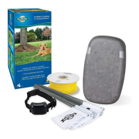
4. Connecting the Lightning Protection Unit to the Transmitter
Cut a length of the supplied white twisted pair wire long
enough to reach from the transmitter LOOP terminals to the
Lightning Protector TRANSMITTER terminals. Do not untwist
the wire.
Strip about 1/4 to 3/8 inch of insulation from both ends of each
twisted white wire. Connect the transmitter terminals labeled
LOOP to the Lightning Protector terminals labeled TRANS-
MITTER. Push the orange release levers on the connector
away from the wire terminal holes to insert or release the wire.
Depress the tab on the Lightning Protector terminal to insert
or release the wire.
5. Plugging in the Power Adapter
Make sure the POWER switch on the transmitter is in the OFF
position. Plug the power adapter into the power outlet on the
right side of the Lightning Protector. Plug the other end of the
power adapter into the POWER jack on the transmitter. Place
the power cord wire under the wire retention tab on the housing.
6. Checking Out the Installation
Make sure your dog is not wearing the collar and no one is
touching the collar probes. Slide the transmitter POWER
switch to the ON position. A green indicator light should illu-
minate on the transmitter indicating a properly connected
boundary loop. If the green indicator light does not illuminate,
refer to the transmitter problems table in the Troubleshoot
Section (Section 8 pg 18).
G.Testing the System
With the boundary wire in place and properly connected and
the collar receiver fully charged, it is time to set the contain-
ment field and test the system.
Note: The collar receiver should NOT be on your dog when
the system is tested.
1. Setting the FIELD SIZE Switch
If you are using a total boundary wire length of 1000 feet or
less, set your FIELD SIZE switch to SM. Otherwise, set it to
LG.
2. Adjusting the Containment Field
The width of the containment field is adjusted using the trans-
mitter's FIELD WIDTH adjustment knob. Start with a low set-
ting. Move the knob to the 9 o'clock position and test the field
width of the system. For the safety of your dog, the field width
of the system must be tested whenever an adjustment is
made to the containment field. Please follow the instructions
below.
3. Field Width Testing the System
Select a section of straight boundary wire that is at least 50
feet long and perform the containment field test at the center
of the selected section. To test the containment field, attach
the test light to the probes and slowly walk the collar receiver
toward the boundary wire. The collar receiver should be held
at the height of your dog's neck with the probes pointed
upward. Listen for the warning sound and watch for the test
light to illuminate. The wider the containment field, the less
chance that a dog can run through the field.
Boundary Wire
Splice
To Lightning Protector
11.
 Loading...