ing plate to the wall using the supplied hardware.
Making sure the POWER switch on the transmitter is in
the OFF position, place 8 AA alkaline backup batteries
(optional, but recommended) in the battery compart-
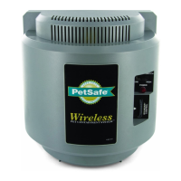
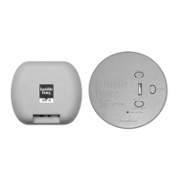
ment on the back of the transmitter. Snap the transmit-
ter onto the mounting plate. Remember to mount your
transmitter in a location where you will be able to hear
any alarms.
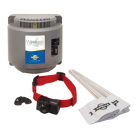
3.Set Up the Collar Receiver (See Section 4.C, pg 9
for details)
In preparation for setting up your boundary loop, the
r e c h a r g e a ble collar receiver must be given a full
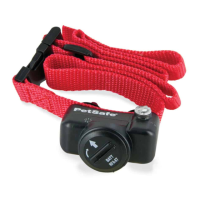
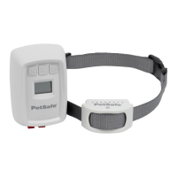
charge. Set the transmitter POWER switch to OFF, set
the FIELD SIZE switch to SM, turn the FIELD WIDTH
knob to MIN, and position the collar receiver in the
charging cradle located on the top of the wall transmit-
ter. Orient the light on the collar receiver toward the end
of the charging cradle marked with an arrow. Cut a
short piece of the green boundary wire (about 6 inches)
and strip about 3/8 inch of insulation from both ends.
Insert the wire ends into the LOOP terminals on the
transmitter. Plug the AC adapter into the power jack on
the transmitter and plug the adapter into a nearby 110-
volt household outlet. Set the transmitter POW E R
switch to the ON position to charge the collar. The
transmitter light will flash green approximately every
two seconds while charging. A full charge requires 14
hours. When charging is complete, the light on the
transmitter will appear solid green. If the green light is
not blinking, make sure the receiver is oriented proper-
ly in the charging cradle, be sure the transmitter is
turned on and check all connections. After the receiver
has been fully charged, set the POWER switch to the
OFF position, remove the short piece of boundary wire,
and unplug the AC adapter from the wall outlet.
NOTE: The transmitter will not recharge the collar
receiver if the loop wire is not installed.
4. Plan the Boundary Wire Placement (See Section
4.D, pg 9 for details)
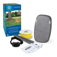
For the system to work properly, the wire must make
one continuous loop. When placing the wire, keep in
mind that you will want at least an 8- to 12-foot contain-
ment field (8 to 12 feet on each side of the wire). Use
the pre-twisted wire from the transmitter to the Lightning
Protector and from the Lightning Protector out to the
exterior loop wire.
5.Place the Wire (See Section 4.E, pg 10 for details)
Place your boundary wire on top of the ground following
the tips listed in Section 4.D. Use the supplied water-
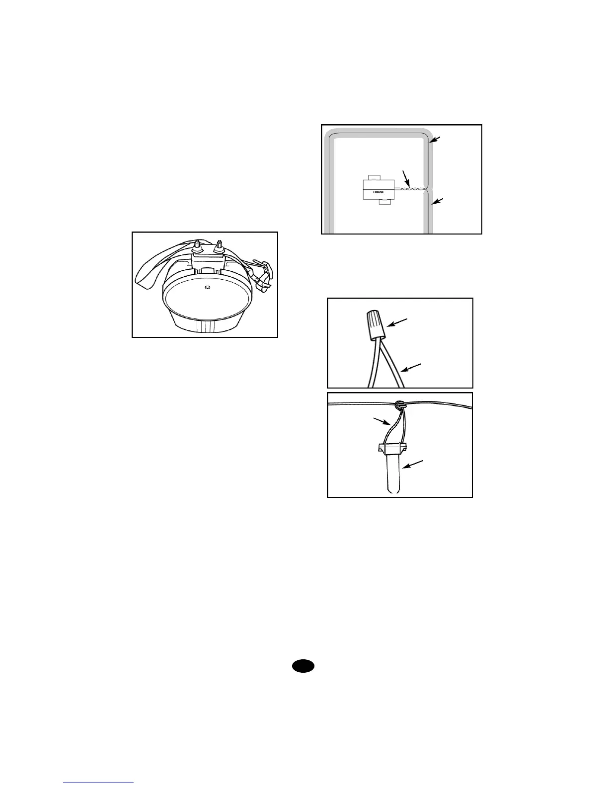
proof splices to make proper connections. To use the
splices, strip 5/8” of insulation from the ends of the
wires you are joining.With the ends of the wires even
and together, place the wire nut over the wire ends and
turn the wire nut clockwise until it is securely fastened.
Snap open the hinged lid of the gell filled capsule and
insert the wire nut as deeply as possible into the water-
proof gel.Snap the lid shut, making sure the wires exit
the splice on either side. Tie a knot in the wires as
shown in the diagram to prevent them from pulling out
of the gell filled capsule when the wire is buried.
DO NOT BURY THE WIRE UNTIL YOU HAVE TESTED
3.
Twisted pair to transmitter;
cancels containment field
Boundary wire
Containment
field (invisible);
8 - 12’width;
follows loop of
wire along
entire length
Wire nut
Wire
Gell filled
capsule
Wire