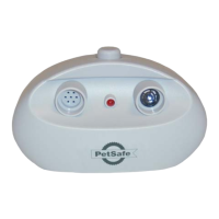
1. Remove the existing pre-twisted wire pair from the
lightning protector LOOP connector by pressing the red
release levers on the connector and pulling the wires
free from the unit.
2. Insert both ends of the 6-foot wire into the LOOP
connector on the lightning protector and recheck the
transmitter status light and alarm.
a. If the status light is green and the alarm is off, the
problem is in the boundary wire. Check for visible
damage to the wire at the entry into the house.If none
is observed, perform the Wire Break Location Test
Procedure to find and correct the wire break (Sec.B).
b. If the status light is still flashing red and the alarm
is on, remove the 6-inch wire, reconnect the bound-
ary wire to the lightning protector and continue with
the following steps.
3. Remove the existing pre-twisted wire pair from the
transmitter LOOP connector by pushing the orange
release levers on the connector away from the wires
and remove the two wires from the transmitter.
4. Insert both ends of the 6-foot wire into the LOOP
connector on the transmitter and recheck the transmit-
ter status light and alarm.
a. If the status light is green and the alarm is off, the
problem is in the lightning protector.The lightning pro-
tector has a lifetime warranty.Contact Invisible Fence
at 1-800-688-4364 for a warranty replacement.
b. If the status light is still flashing red and the alarm
is on, the malfunction is in the transmitter. Contact
Invisible Fence at 1-800-688-4364 for assistance.
B.Wire Break Location Test Procedure
The wire break location test procedure is used to locate
broken or damaged sections of the containment bound-
ary wire. To locate wire breaks in the loop installation,
you will need a portable AM radio and a RF Choke
(available at Radio Shack
®
; part number 273-102).
Once you have these items, follow these steps:
1. Disconnect the transmitter power by unplugging the
power adapter from the outlet.
2. Disconnect the boundary wires from the Lightning
Protector LOOP terminals. (If you have a digital multi-
meter available, confirm the existence of a complete
wire break by measuring the continuity between the two
wires.If the wire is intact the total resistance measured
for 18 AWG wire should be 0.00639 Ohms per foot mul-
tiplied by the total length of the wire in feet that you
installed in your system, i.e. 0.00639 Ω/ft x 700 feet =
4.473 ohms. NOTE: Measuring the continuity will not
detect the presence of nicks or scrapes in the wire insu-
lation.) The following tests must be performed to locate
these damaged sections.
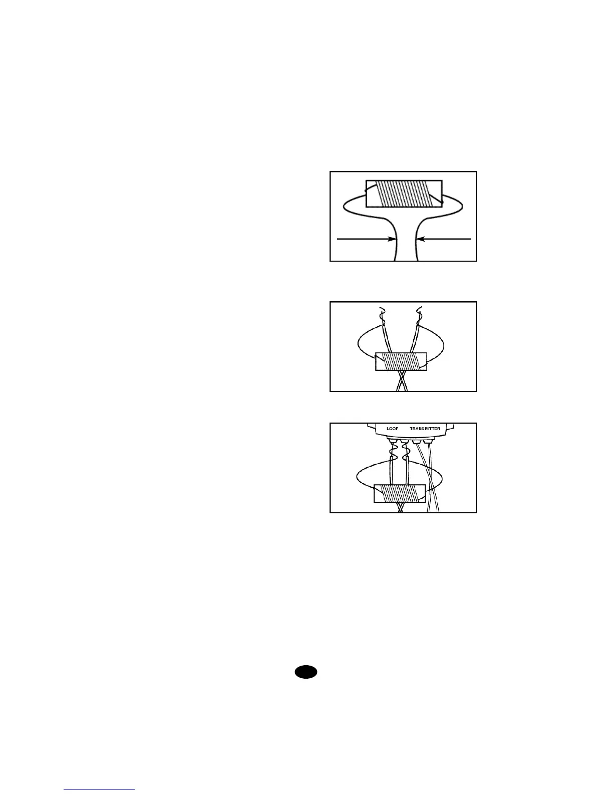
3. Bend the leads of the RF Choke into the shape
shown in figure.
4. Carefully wrap the RF Choke leads around the
boundary wire leads as shown.
5. Plug the RF Choke and boundary wire leads into the
loop terminals on the lightning protector as shown.
6. Plug the power adapter back into the Lightning
Protector outlet.
7. Set the portable AM radio to AM-60 or AM-600
(whichever one has no station).
8. Adjust the transmitter FIELD WIDTH knob high
enough to obtain a signal on the portable radio when
holding the radio over the containment boundary wire.
The signal that you receive is short static pulses.
9. The signal should be absent on the twisted wire por-
tions because twisting cancels the signal.
10. Hold the radio 1 to 2 feet off the ground and swing
the radio (side to side, left to right) over the wire as you
walk along the boundary.
20.
1/4”