wall stud, drill 3/32-inch diameter pilot holes at the marked
locations.
Fasten the mounting plate to the mounting location using the
supplied screws.
3 . Install Power Backup Batteries (Optional bu t
Recommended).
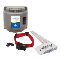
Your system's transmitter includes the means for installing
backup batteries so the system will remain functional for a lim-
ited time, even if your home experiences a power failure.
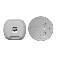
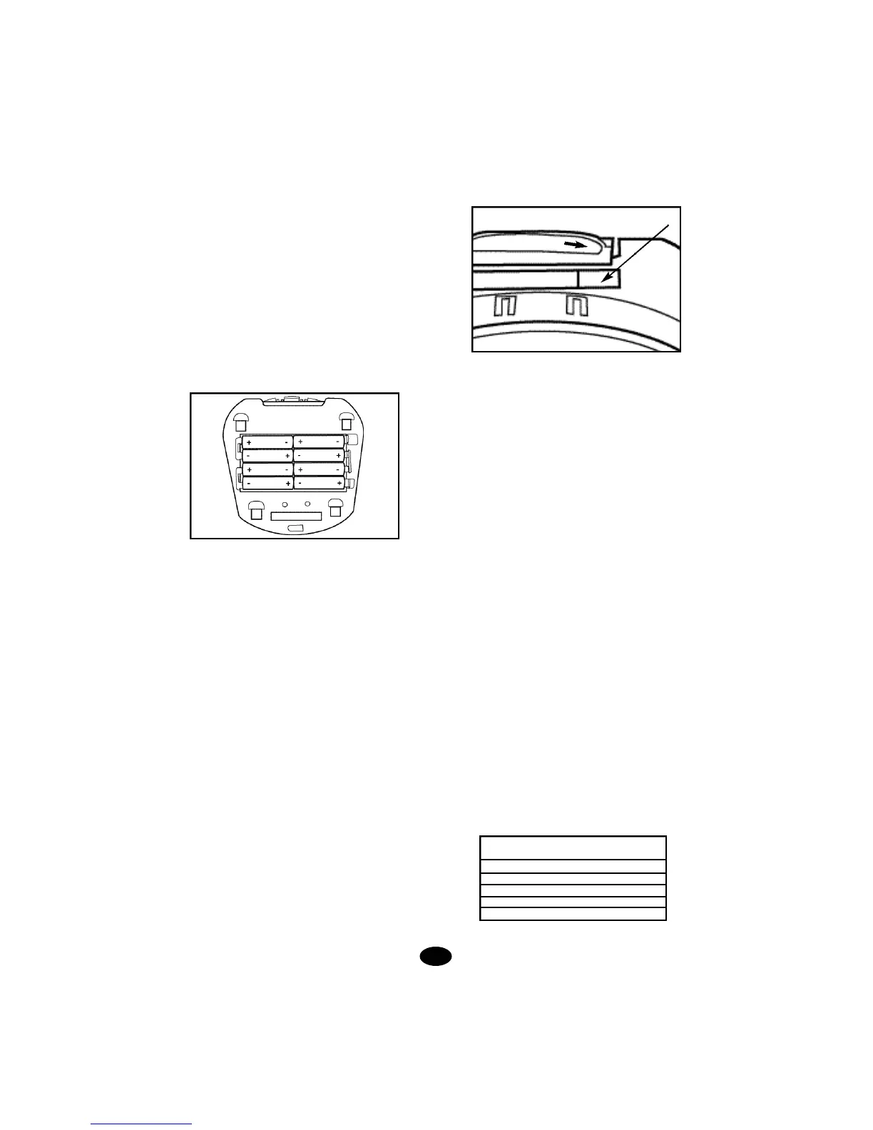
Set the POWER switch under the transmitter's front cover to
the OFF position. With the mounting plate removed, turn the
transmitter over to reveal the backup battery compartment.
Install eight (8) AA alkaline batteries according to the polarity
markings inside the battery compartment.
Set the BATTERY BACKUP MONITOR switch to the ON posi-
tion. If you choose not to install the backup batteries, set the
BATTERY BACKUP MONITOR switch to the OFF position to
disable the low battery alert.
4. Install the Transmitter on the Wall.
Snap the transmitter onto the mounting plate. At the pre-
marked location where the containment wires will enter the
home, drill a 1/4-inch hole from the inside through the wall or
corner of a windowsill or door frame. A slight downward angle
will help the wire to curve downward outside and keep water
out.
A masonry bit can be used to drill through cinderblock or
through the joint crack on brick or stone walls. A regular 1/4-
inch drill bit can be used if the house is of wooden construc-
tion with vinyl or aluminum siding. In these cases, you may
want to drill from the outside for exterior aesthetics.
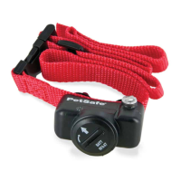
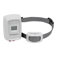
C.Setting Up the Collar Receiver - In preparation for setting
up your boundary loop, the rechargeable collar receiver must
be given a full charge.
1. Set the transmitter POWER switch to OFF.
2. Set the FIELD SIZE switch to SM.
3. Turn the FIELD WIDTH knob to MIN.
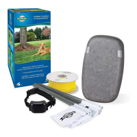
4. Position the collar receiver in the charging cradle located on
the top of the wall transmitter. Orient the light on the collar
receiver toward the end of the charging cradle marked with an
arrow and identified on the label.
5. Cut a short piece of the green boundary wire (about 6 inch-
es long) and strip about 3/8 inch of insulation from both ends.
Insert the wire ends into the LOOP terminals on the transmit-
ter.NOTE:This wire is temporarily installed to perform the ini-
tial set up charging of the collar receiver. The transmitter will
not charge the collar receiver if the loop wire is not installed.
6. Plug the AC adapter into the POWER jack on the transmit-
ter and plug the adapter into a nearby 110-volt household out-
let.
7. Set the transmitter POWER switch to the ON position to
charge the collar. The transmitter light will flash green approx-
imately every two seconds while charging and a high fre-
quency charge tone will be heard from the transmitter. If the
green light is not blinking, make sure the receiver is oriented
properly in the charging cradle, be sure the transmitter is
turned on and check all connections. A full charge requires
14 hours. When charging is complete, the light on the trans-
mitter will appear solid green. After the receiver has been fully
charged, set the POWER switch to the OFF position, remove
the short piece of boundary wire and unplug the AC adapter
from the wall outlet.
D. Planning the Placement of the Boundary Wire -With the
wall transmitter installed and the hole drilled for the wires,
begin positioning the boundary wire according to your layout.
Listed below are some helpful instructions and tips.
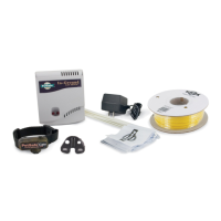
1. Amount of Wire
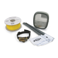
Your system includes 700 feet of boundary wire and 100 feet
of pre-twisted wire. For yards requiring more wire, boundary
kits are available from Invisible Fence at 1-800-688-4364. It
is important that the same gauge wire be used throughout the
installation. Here are some examples of wire coverage:
The above figures assume a rectangular layout and actual
footage may vary.
9.
collar receiver light to this end
Acres Linear Feet
Needed
1 850
2 1200
3 1500
4 1700
5 1900