THE SYSTEM AND ARE SURE IT IS WORKING
PROPERLY. TAKE CARE NOT TO NICK OR SCRAPE
THE WIRE INSULATION DURING INSTALLATION. AN
INTERMITTENT SIGNAL OR NO SIGNAL MAY
OCCUR.
6. Make the Final Connections (See Section 4.F, pg
10 for details)
Determine where the boundary wire will enter the build-
ing and drill a 1/4 inch hole through the wall, making
sure there are no wires, cables or pipes in the area you
are drilling. Plug the Lightning Protector into a nearby
standard, grounded 110-volt household outlet. Use the
supplied white twisted pair wire to connect your bound-
ary wire to the LOOP terminals on the Lightning
Protector and to connect the TRANSMITTER terminals
on the Lightning Protector to the LOOP terminals on the
transmitter. Making sure the power switch on the trans-
mitter is in the OFF position, plug the power adapter
into the Lightning Protector and plug the other end of
the power adapter into the POWER jack on the trans-
mitter. Set the FIELD SIZE switch to SM if you are
using less than 1000 feet of boundary wire or to LG if
the boundary wire is longer than 1000 feet. Verify that
your dog is not wearing the collar and no one is touch-
ing the collar receiver probes, set the FIELD WIDTH
knob to MIN and slide the transmitter POWER switch
into the ON position. A green indicator light should illu-
minate on the transmitter indicating a properly connect-
ed boundary loop. If the green indicator light does not
illuminate, refer to the Section 8, pg 16 to troubleshoot
the installation.
7.Test the system (See Section 4.G, pg 11 for details)
Make sure no one is touching the collar receiver
probes. Set the transmitter's FIELD WIDTH adjustment
knob to the 9 o'clock position and set the transmitter
POWER switch to the ON position. Attach the test light
to the probes and slowly walk the collar receiver toward
the center of a 50 foot straight section of the boundary
wire with the collar receiver held at the height of your
dog's neck with the probes pointed upward. Listen for
the warning sound and watch for the test light to illumi-
nate. The containment field should extend at least 8 to
12 feet on each side of the wire. To increase the field
width, rotate the FIELD WIDTH adjustment knob clock-
wise and recheck the distance the signal is broadcast-
ing from the wire.To decrease rotate Field Width count-
er clockwise; recheck.Repeat this procedure until you
are satisfied with the width of the correction field
throughout the installation.
8. Bury the Boundary Wire and Place Flags (See
Section 4.H, pg 12 for details)
Turn off the transmitter and disconnect the AC adapter
from the Lightning Protector. Bury the wire about 3 to 4
inches deep where the wire first enters the ground near
the transmitter and continue around the path of the loop
wire at a depth of at least 1 inch (you may wish to rent
a slit trencher for this purpose). Be careful you don't
nick the wire insulation as you place the wire in the
ground. Leave some slack in the wire to compensate
for expansion and contraction due to tempera t u r e
changes. Repeat the test from Step 7 until you are sat-
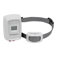
isfied with the field width setting.As you approach the
boundary wire, place a flag 3 to 4 feet inside the point
where the receiver first detects the warning sound.
Continue placing the flags at 6 to 8 foot intervals around
the entire containment area using this technique. Don't
forget to caulk and seal the interior and exterior holes
you made for the wire to prevent damage from mois-
ture. You are now ready to proceed with Sections 5
through 7 for detailed instructions on using the system
and training your dog.
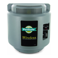
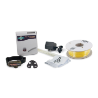
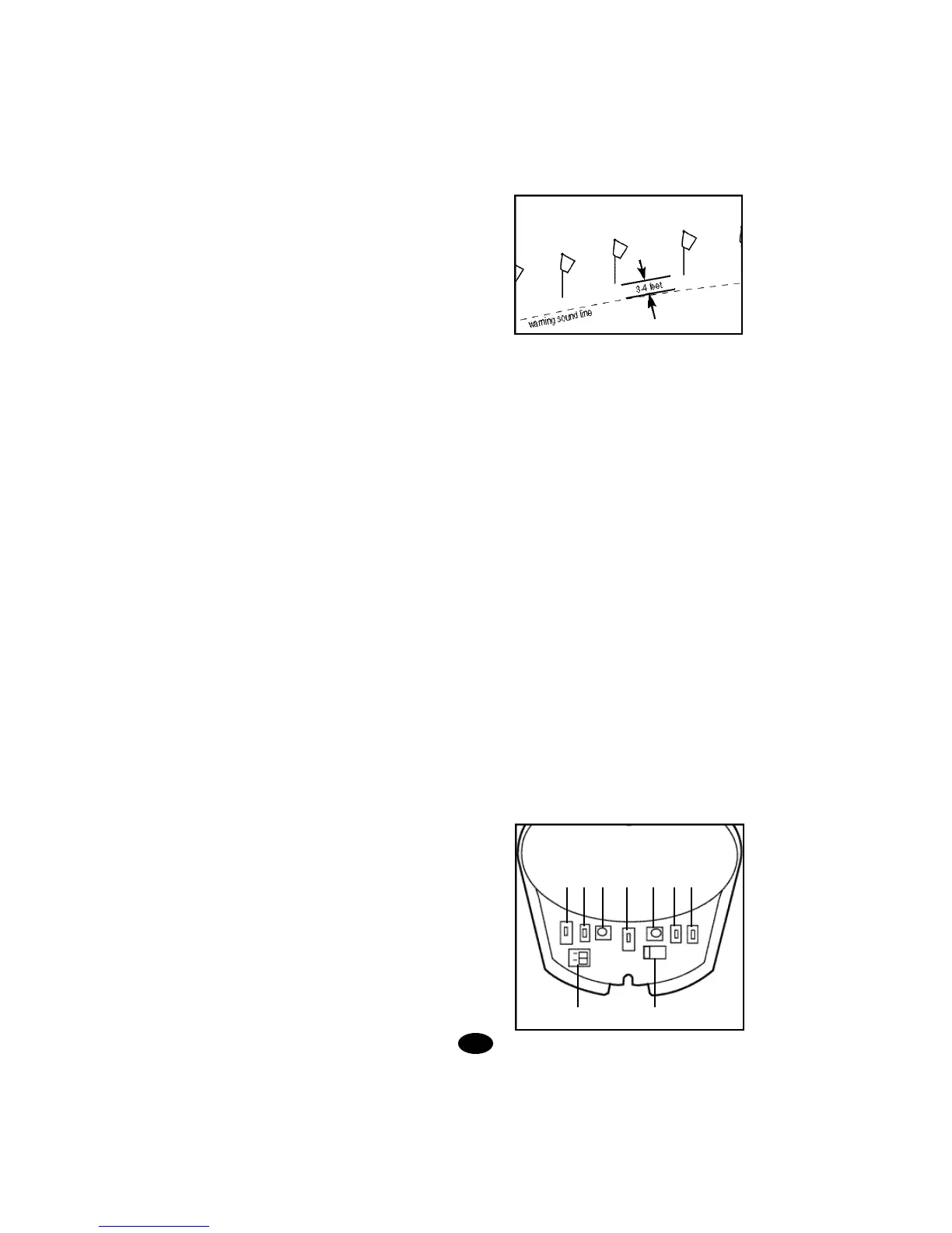
SECTION 1.
THE WALL-MOUNT TRANSMITTER
The wall-mount transmitter is your system's control cen-
ter and works with the collar receiver and boundary wire
to keep your dog safely contained within an area you
select. The front cover of the wall transmitter lifts up to
reveal switches that will customize your containment
system.
1. 2. 3. 4. 5. 6. 7.
8. 9.
4.
Containment Field
Safe Zone