(3)
Timing the Feed Across Motion
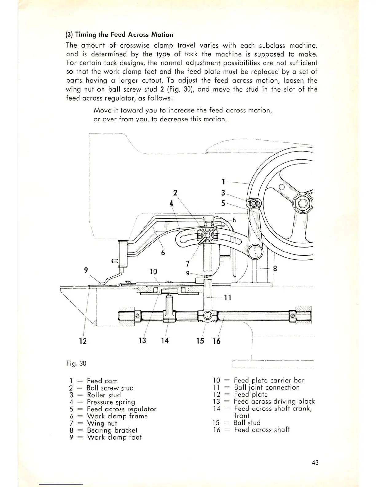
The
amount
of crosswise clamp travel varies with each subclass machine,
and
is
determined
by the type of tack the machine is
supposed
to make.
For certain tack designs, the normal adjustment possibilities
are
not sufficient
so that the work clamp feet and the feed plate must be replaced by o set of
parts having a larger cutout. To
adjust
the
feed
across motion, loosen the
wing nut on ball screw stud 2 (Fig. 30),
and
move the stud in the slot of the
feed
across
regulator, as follows:
Move it
toward
you to increase the feed across motion,
or over from you, to decrease this motion.
Fig. 30
1 =
Feed
com
2 =
Ball
screw
stud
3 =
Roller
stud
4 =
Pressure
spring
5 = Feed across
regulator
6 =
Work
clamp
frame
7 =
Wing
nut
8 = Beoring bracket
9 =
Work
clomp
foot
10 = Feed plate carrier
bar
11 = Ball joint
connection
12 = Feed
plate
13 =
Feed
across
driving block
14 =
Feed
across
shaft
crank,
front
15
=
Ball
stud
16 =
Feed
across
shaft
43