Characteristics
Min flow
1 m
3
/h
If using in sniffer with the Smart probe, minimum flow rate = 3 m
3
/h
Max flow
100 m
3
/h
A higher flow rate will not improve the performance of the leak detector + backing
pump assembly.
5.8.2 Connection of the backing pump
The leak detector must be connected to a backing pump before being switched on.
2 DN 25 ISO-KF connections are available to connect the backing pump.
●
1 connection at the rear (configuration on delivery)
●
1 connection under the frame
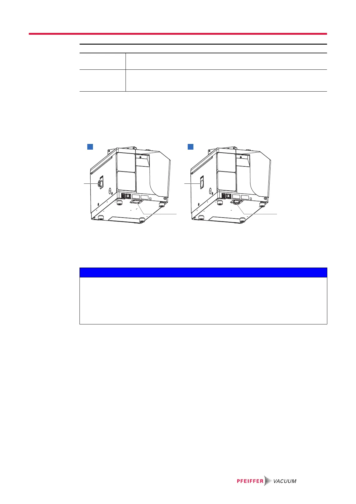
A Connection at the rear 1 DN 25 ISO-KF connection tubing
DN 25 ISO-KF plastic blanking plate (supplied with the detector)
B Connection underneath 2 Filler cap
Backing pump connection under the frame
NOTICE
Using an external backing pump
It is the user's responsibility to protect the detector from any contamination or deterioration that may
be caused by the connected external backing pump (particles, backscattering of oil in the detector,
for example).
►
Any contamination or deterioration of the detector due to the connected external backing pump
will not be recognized by the manufacturer under warranty.
1.
Remove the front cover (see chapter "Disassembly/reassembly of the front cover" in the mainte-
nance instructions).
2. Remove the rear cover (see chapter "Disassembly/reassembly of the rear cover" in the mainte-
nance instructions).
3. Remove the filler cap, which is clipped on, from the frame ([A]).
4. Remove the 4 M6x16 fixing screws and their washers from the connection tubing ([A]).
5. Release the connection tubing and replace the 4 M6x16 fixing screws and their washers ([A]).
6. Remove the 4 M6x12 fixing screws and their washers ([A]).
7. Place the connection tubing in its housing on the frame and secure it with the 4 M6x12 fixing
screws and their washers ([B]).
8. Refit the covers.
9. Clip the filler cap into the opening of the rear cover ([C]).
10. Fit the DN 25 ISO-KF plastic blanking plate (supplied with the detector) onto the connection tubing
([C]):
●
as long as the detector is not connected to an external backing pump
●
any time the detector is dispatched.
Installation
27/108